Toyota Camry (XV70): DCM Data Signal Circuit between Navigation ECU and DCM
DESCRIPTION
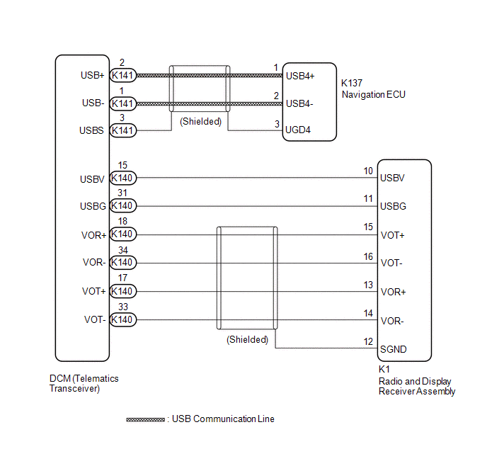
This circuit is used to send and receive signals between the DCM (Telematics Transceiver) and radio and display receiver assembly or navigation ECU.
WIRING DIAGRAM
PROCEDURE
| 1. |
CHECK HARNESS AND CONNECTOR (RADIO AND DISPLAY RECEIVER ASSEMBLY - DCM (TELEMATICS TRANSCEIVER)) |
(a) Disconnect the K140 DCM (Telematics Transceiver) connector.
(b) Disconnect the K1 radio and display receiver assembly connector.
(c) Measure the resistance according to the value(s) in the table below.
Standard Resistance:
|
Tester Connection | Condition |
Specified Condition |
|---|---|---|
|
K140-31 (USBG) - K1-11 (USBG) |
Always | Below 1 Ω |
|
K140-17 (VOT+) - K1-13 (VOR+) |
Always | Below 1 Ω |
|
K140-15 (USBV) - K1-10 (USBV) |
Always | Below 1 Ω |
|
K140-33 (VOT-) - K1-14 (VOR-) |
Always | Below 1 Ω |
|
K140-34 (VOR-) - K1-16 (VOT-) |
Always | Below 1 Ω |
|
K140-18 (VOR+) - K1-15 (VOT+) |
Always | Below 1 Ω |
|
K140-31 (USBG) or K1-11 (USBG) - Body ground |
Always | 10 kΩ or higher |
|
K140-17 (VOT+) or K1-13 (VOR+) - Body ground |
Always | 10 kΩ or higher |
|
K140-15 (USBV) or K1-10 (USBV) - Body ground |
Always | 10 kΩ or higher |
|
K140-33 (VOT-) or K1-14 (VOR-) - Body ground |
Always | 10 kΩ or higher |
|
K140-34 (VOR-) or K1-16 (VOT-) - Body ground |
Always | 10 kΩ or higher |
|
K140-18 (VOR+) or K1-15 (VOT+) - Body ground |
Always | 10 kΩ or higher |
| NG | .gif) | REPAIR OR REPLACE HARNESS OR CONNECTOR |
|
.gif)
| 2. |
CHECK HARNESS AND CONNECTOR (NAVIGATION ECU - DCM (TELEMATICS TRANSCEIVER)) |
| (a) Disconnect the K141 DCM (Telematics Transceiver) connector. |
|
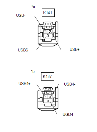
(b) Disconnect the K137 navigation ECU connector.
(c) Measure the resistance according to the value(s) in the table below.
Standard Resistance:
|
Tester Connection | Condition |
Specified Condition |
|---|---|---|
|
K141-1 (USB-) - K137-2 (USB4-) |
Always | Below 1 Ω |
|
K141-2 (USB+) - K137-1 (USB4+) |
Always | Below 1 Ω |
|
K141-3 (USBS) - K137-3(UGD4) |
Always | Below 1 Ω |
|
K141-1 (USB-) or K137-2 (USB4-) - Body ground |
Always | 10 kΩ or higher |
|
K141-2 (USB+) or K137-1 (USB4+) - Body ground |
Always | 10 kΩ or higher |
|
K141-3 (USBS) or K137-3 (UGD4) - Body ground |
Always | 10 kΩ or higher |
| OK | | PROCEED TO NEXT SUSPECTED AREA SHOWN IN PROBLEM SYMPTOMS TABLE |
| NG | | REPAIR OR REPLACE HARNESS OR CONNECTOR |
READ NEXT:
 Parts Location
PARTS LOCATION ILLUSTRATION
*1 INNER REAR VIEW MIRROR ASSEMBLY
- GARAGE DOOR OPENER *2
INSTRUMENT PANEL JUNCTION BLOCK ASSEMBLY - ECU-DCC NO. 2 FUSE
- ECU-IG1 NO. 3 FUSE
SEE MORE:
Multi-axis Acceleration Sensor Module "A" Supply Voltage Circuit Voltage Out of Range (C14D71C)
DESCRIPTION The airbag sensor assembly has a built-in yaw rate and acceleration sensor and detects the vehicle condition.
This DTC is stored when the skid control ECU (brake actuator assembly) receives a sensor supply voltage malfunction signal from the yaw rate and acceleration sensor (airbag sen
Precaution
PRECAUTION
NOTICE:
This vehicle is equipped with an SRS (Supplemental Restraint System). Failure to carry out service operations in the correct sequence could cause the SRS to unexpectedly deploy during servicing. This may cause a serious accident. Before servicing (including inspection, repla
