Toyota Camry (XV70): Parts Location
PARTS LOCATION
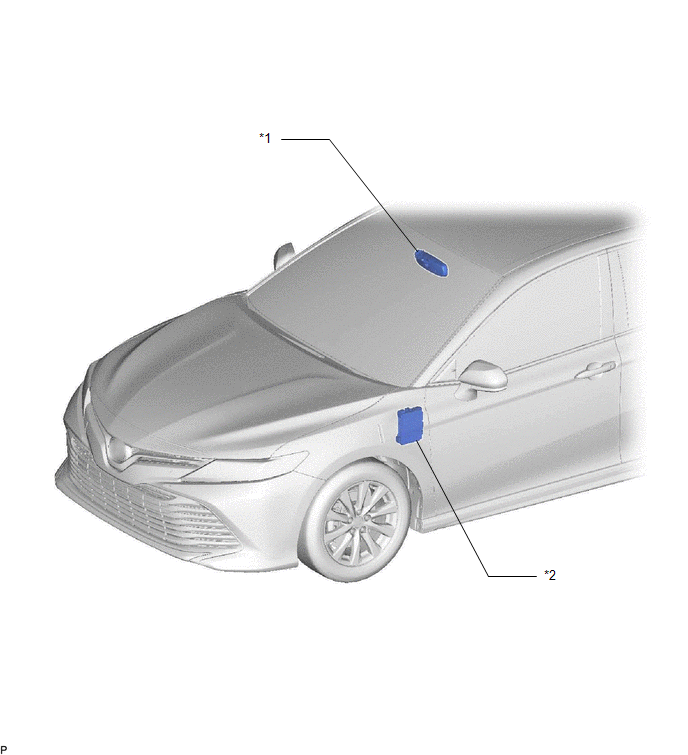
ILLUSTRATION
|
*1 | INNER REAR VIEW MIRROR ASSEMBLY - GARAGE DOOR OPENER | *2 |
INSTRUMENT PANEL JUNCTION BLOCK ASSEMBLY - ECU-DCC NO. 2 FUSE - ECU-IG1 NO. 3 FUSE |
READ NEXT:
 System Diagram
SYSTEM DIAGRAM
System Description
SYSTEM DESCRIPTION DESCRIPTION (a) A maximum of 3 kinds of transmitter code based systems (example: garage doors, gates and entry gates) can be registered with the vehicle garage door opener. After re
Registration
REGISTRATION PROCEDURE 1. REGISTER TRANSMITTER CODE
HINT:
The vehicle garage door opener records transmitter codes for systems such as garage doors, gates, entry gates, door locks, home lighting
SEE MORE:
Components
COMPONENTS ILLUSTRATION
*1 FRONT DOOR OPENING TRIM WEATHERSTRIP
*2 FRONT NO. 2 SPEAKER ASSEMBLY
*3 FRONT PILLAR GARNISH
*4 NO. 1 INSTRUMENT PANEL SPEAKER PANEL
*5 CLIP
- -
● Non-reusable part
- -
Left Electric Parking Brake Actuator Control (C060B00,C060B11)
DESCRIPTION
DTC No. Detection Item
DTC Detection Condition Trouble Area
Memory Note
C060B00 Left Electric Parking Brake Actuator Control
Diagnosis Condition:
-
Malfunction Status:
When the ECU power supply is normal, a malfunction in the electri
© 2023-2026 Copyright www.tocamry.com
