
Toyota Camry (XV70): System Diagram
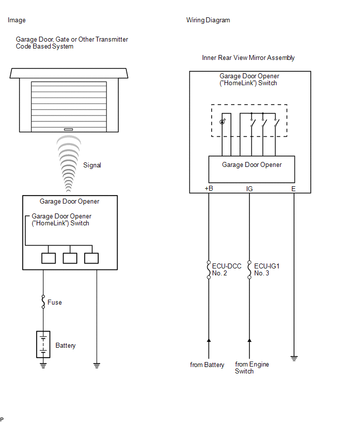
SYSTEM DIAGRAM
READ NEXT:
 System Description
SYSTEM DESCRIPTION DESCRIPTION (a) A maximum of 3 kinds of transmitter code based systems (example: garage doors, gates and entry gates) can be registered with the vehicle garage door opener. After re
Registration
REGISTRATION PROCEDURE 1. REGISTER TRANSMITTER CODE
HINT:
The vehicle garage door opener records transmitter codes for systems such as garage doors, gates, entry gates, door locks, home lighting
On-vehicle Inspection
ON-VEHICLE INSPECTION PROCEDURE
1. INSPECT GARAGE DOOR OPENER
(a) Press each garage door opener ("HomeLink") switch and check that the ("HomeLink") indicator light turns on. If one or more of
SEE MORE:
4WD Control ECU Communication Stop Mode
DESCRIPTION
Detection Item Symptom
Trouble Area 4WD Control ECU Communication Stop Mode
Any of the following conditions are met:
Communication stop for "Four Wheel Drive Control" is indicated on the "Communication Bus Check" screen of the Techstream.
Click here
Basic Inspection
CAUTION / NOTICE / HINT When a malfunction is not confirmed by the DTC check, troubleshooting should be carried out for all circuits considered to be possible causes of the problem. In many cases, by carrying out the basic engine check shown in the following procedure, the location of the problem ca
© 2023-2026 Copyright www.tocamry.com
