Toyota Camry (XV70): On-vehicle Inspection
ON-VEHICLE INSPECTION
PROCEDURE
1. INSPECT GARAGE DOOR OPENER
| (a) Press each garage door opener ("HomeLink") switch and check that the ("HomeLink") indicator light turns on. If one or more of the garage door opener ("HomeLink") switches does not turn on the ("HomeLink") indicator light, check the condition of the fuse and wire harness. if the wire of the fuse is broken or the wire harness is malfunctioning repair or replace it. If not, replace the inner rear view mirror assembly (garage door opener). Click here |
|
.png)
2. INSPECT GARAGE DOOR OPENER REGISTRATION AND TRANSMITTING
HINT:
Use the "HomeLink" tester and a tester transmitter for this test. First clear the customer transmitter codes, and then register the tester transmitter code.
Click here .gif)
(a) Check if the tester transmitter code was successfully registered.
HINT:
- Any garage door opener ("HomeLink") switch can be pressed.
- If the code cannot be registered, replace the inner rear view mirror assembly (garage door opener).
Click here
(b) Apply battery voltage to the "HomeLink" tester as shown in the illustration.
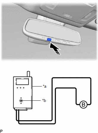
|
*a | "HomeLink" Tester |
|
*b | Red LED |
.png) |
Press |
(c) Press a garage door opener ("HomeLink") switch. Check if the red LED of the "HomeLink" tester illuminates.
HINT:
If the red LED does not illuminate, replace the inner rear view mirror assembly (garage door opener).
Click here
(d) When the inspection is complete, register the customer transmitter code(s) again.
HINT:
- Registration of the customer transmitter code(s) may not be possible in the service facility if the customer's transmitters are not available or if any of the buttons are used for rolling code-type systems.
- Refer to the Owner's Manual for additional information about registration (programming) of transmitter codes.
READ NEXT:
 Antenna Cord
ComponentsCOMPONENTS ILLUSTRATION
*1 ANTENNA CORD SUB-ASSEMBLY
*2 INSTRUMENT PANEL SAFETY PAD SUB-ASSEMBLY
*3 NO. 2 SIDE DEFROSTER NOZZLE DUCT
*4 NO. 3 HEATER TO
SEE MORE:
Left Rear Wheel Speed Sensor Signal Stuck High (C050C24)
DESCRIPTION Refer to DTC C050C12 Click here
DTC No. Detection Item
DTC Detection Condition Trouble Area
C050C24 Left Rear Wheel Speed Sensor Signal Stuck High
The speed sensor signal is not within the specified range for 5 seconds or more.
Rear speed sensor L
Camera ECU Malfunction (C1610)
DESCRIPTION This DTC is stored when a malfunction occurs in the parking assist monitor system*1 or panoramic view monitor system*2.
DTC No. Detection Item
DTC Detection Condition Trouble Area
C1610 Camera ECU Malfunction
Malfunction occurs in the parking assist mo
