Toyota Camry (XV70): On-vehicle Inspection
ON-VEHICLE INSPECTION
CAUTION / NOTICE / HINT
HINT:
- Use the same procedure for the RH side and LH side.
- The following procedure is for the LH side.
PROCEDURE
1. REMOVE REAR WHEEL
Click here
.gif)
2. SEPARATE REAR DISC BRAKE CALIPER ASSEMBLY
Click here
3. REMOVE PARKING BRAKE SHOE ADJUSTING HOLE PLUG
Click here
4. REMOVE REAR DISC
Click here
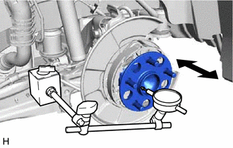
5. INSPECT REAR AXLE HUB BEARING LOOSENESS
| (a) Using a dial indicator with magnetic base, check for looseness near the center of the rear axle hub. Maximum Looseness: 0.05 mm (0.00196 in.) NOTICE:
HINT: If the looseness exceeds the maximum, replace the rear axle hub and bearing assembly. |
|
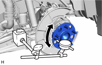
6. INSPECT REAR AXLE HUB RUNOUT
| (a) Using a dial indicator with magnetic base, check for runout on the surface of the rear axle hub outside the rear axle hub bolts. Maximum Runout: 0.05 mm (0.00196 in.) NOTICE:
HINT: If the runout exceeds the maximum, replace the rear axle hub and bearing assembly. |
|
7. INSTALL REAR DISC
Click here
8. INSTALL PARKING BRAKE SHOE ADJUSTING HOLE PLUG
Click here
9. INSTALL REAR DISC BRAKE CALIPER ASSEMBLY
Click here
10. ADJUST PARKING BRAKE
Click here
11. INSTALL REAR WHEEL
Click here
READ NEXT:
 Removal
REMOVAL CAUTION / NOTICE / HINT
HINT:
Use the same procedure for the RH side and LH side.
The following procedure is for the LH side.
PROCEDURE 1. REMOVE REAR WHEEL Click here
2.
Installation
INSTALLATION CAUTION / NOTICE / HINT
HINT:
Use the same procedure for the RH side and LH side.
The following procedure is for the LH side.
PROCEDURE 1. INSTALL REAR AXLE HUB AND BEARING
SEE MORE:
Installation
INSTALLATION PROCEDURE 1. INSTALL CLEARANCE WARNING ECU ASSEMBLY
(a) Engage the claw to install the clearance warning ECU assembly as shown in the illustration.
Install in this Direction 2. INSTALL ECU INTEGRATION BOX RH
Click here 3. INSTALL LOWER INSTRUMENT PANEL SUB-ASSE
Fail-safe Chart
FAIL-SAFE CHART Automatic Cancel Control (a) When the vehicle is being driven in constant speed control mode and any of the following malfunctions occur, control of vehicle speed by the dynamic cruise control system is canceled.
Auto Cancel Condition Multi-information Display
Master War
