Toyota Camry (XV70): Brake Hold Switch
Components
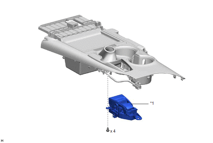
COMPONENTS
ILLUSTRATION
|
*1 | BRAKE HOLD SWITCH (ELECTRIC PARKING BRAKE SWITCH ASSEMBLY) |
- | - |
Removal
REMOVAL
PROCEDURE
1. PRECAUTION
Click here .gif)
2. REMOVE REAR UPPER CONSOLE PANEL SUB-ASSEMBLY
Click here
3. REMOVE BRAKE HOLD SWITCH (ELECTRIC PARKING BRAKE SWITCH ASSEMBLY)
| (a) Disengage the clamp and guide. |
|
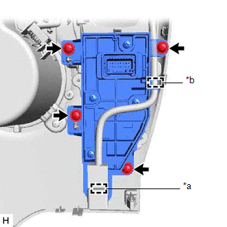
(b) Remove the 4 screws and brake hold switch (electric parking brake switch assembly).
Inspection
INSPECTION
PROCEDURE
1. INSPECT BRAKE HOLD SWITCH (ELECTRIC PARKING BRAKE SWITCH ASSEMBLY)
| (a) Make sure that there is no looseness in the locking part and the connecting part of the connector. OK: The connector is securely connected. |
|
(b) Disconnect the brake hold switch (electric parking brake switch assembly) connector.
(c) Check both the connector case and the terminal for deformation and corrosion.
OK:
No deformation or corrosion.
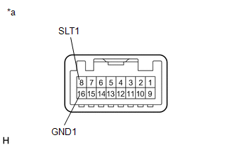
(d) Measure the resistance according to the value(s) in the table below.
Standard Resistance:
|
Tester Connection | Condition |
Specified Condition |
|---|---|---|
|
8 (SLT1) - 16 (GND1) |
Switch pushed | Below 1 Ω |
|
8 (SLT1) - 16 (GND1) |
Switch not pushed | 10 kΩ or higher |
If the result is not as specified, replace the brake hold switch (electric parking brake switch assembly).
Installation
INSTALLATION
PROCEDURE
1. INSTALL BRAKE HOLD SWITCH (ELECTRIC PARKING BRAKE SWITCH ASSEMBLY)
(a) Install the brake hold switch (electric parking brake switch assembly) with the 4 screws.
(b) Engage the guide and clamp.
2. INSTALL REAR UPPER CONSOLE PANEL SUB-ASSEMBLY
Click here .gif)
READ NEXT:
 Components
COMPONENTS ILLUSTRATION
*1 FRONT FENDER LINER
*2 FRONT SPEED SENSOR
*3 FRONT WHEEL OPENING EXTENSION PAD
*4 FRONT FLEXIBLE HOSE
Tightening torque f
Removal
REMOVAL CAUTION / NOTICE / HINT
HINT:
Use the same procedure for the RH side and LH side.
The following procedure is for the LH side.
The front speed sensor rotor is a component of the f
SEE MORE:
Pressure Control Solenoid "A" Actuator Stuck Off (P07457F)
DESCRIPTION Based on signals from the transmission revolution sensors (NT and NC), the actual gear is detected.
The ECM compares the actual gear with the shift schedule in the ECM memory to detect mechanical malfunctions of the solenoid valves, transmission valve body assembly and automatic transa
Garage door operation indicators
The status of the opening and
closing of a garage door is shown
by the indicators.
Opening
Closing
This function is only available if the
garage door opener motor used is
a compatible device. (To check
device compatibility, refer to
www.HomeLink.com.)
The indicators can operate w
