
Toyota Camry (XV70): Components
COMPONENTS
ILLUSTRATION
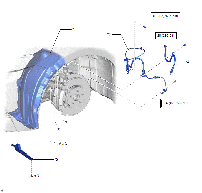
|
*1 | FRONT FENDER LINER |
*2 | FRONT SPEED SENSOR |
|
*3 | FRONT WHEEL OPENING EXTENSION PAD |
*4 | FRONT FLEXIBLE HOSE |
.png) |
Tightening torque for "Major areas involving basic vehicle performance such as moving/turning/stopping" : N*m (kgf*cm, ft.*lbf) |
.png) |
N*m (kgf*cm, ft.*lbf): Specified torque |
READ NEXT:
 Removal
REMOVAL CAUTION / NOTICE / HINT
HINT:
Use the same procedure for the RH side and LH side.
The following procedure is for the LH side.
The front speed sensor rotor is a component of the f
Installation
INSTALLATION CAUTION / NOTICE / HINT
HINT:
Use the same procedure for the RH side and LH side.
The following procedure is for the LH side.
The front speed sensor rotor is a component of
Rear Speed Sensor
ComponentsCOMPONENTS ILLUSTRATION
*A w/o Electric Parking Brake System
- -
*1 PARKING BRAKE SHOE ADJUSTING HOLE PLUG
*2 REAR AXLE HUB AND BEARING ASSEMBLY
SEE MORE:
Installation
INSTALLATION PROCEDURE 1. INSTALL REAR STABILIZER BUSHING
(a) Install the 2 rear stabilizer bushings to the outside of the stoppers on the rear stabilizer bar.
NOTICE: Be sure to install the rear stabilizer bushings so that each cutout faces the front of the vehicle.
HINT: The cutout of
Position Initialization Incomplete (B2343)
DESCRIPTION This DTC is stored when the sliding roof ECU (sliding roof drive gear sub-assembly) has not been initialized.
DTC No. Detection Item
DTC Detection Condition
Trouble Area
B2343 Position Initialization Incomplete
Sliding roof ECU (sliding roof drive g
© 2023-2026 Copyright www.tocamry.com
