Toyota Camry (XV70): Rear Speed Sensor
Components
COMPONENTS
ILLUSTRATION
|
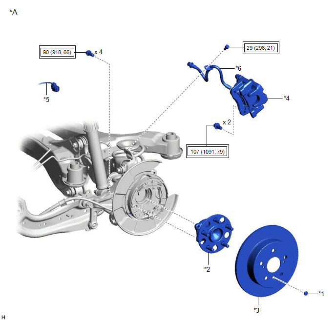
*A | w/o Electric Parking Brake System |
- | - |
|
*1 | PARKING BRAKE SHOE ADJUSTING HOLE PLUG |
*2 | REAR AXLE HUB AND BEARING ASSEMBLY |
|
*3 | REAR DISC |
*4 | REAR DISC BRAKE CALIPER ASSEMBLY |
|
*5 | SKID CONTROL SENSOR WIRE |
*6 | REAR FLEXIBLE HOSE |
.png) |
Tightening torque for "Major areas involving basic vehicle performance such as moving/turning/stopping" : N*m (kgf*cm, ft.*lbf) |
- | - |
ILLUSTRATION
|
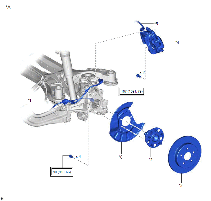
*A | w/ Electric Parking Brake System |
- | - |
|
*1 | NO. 2 PARKING BRAKE WIRE ASSEMBLY |
*2 | REAR AXLE HUB AND BEARING ASSEMBLY |
|
*3 | REAR DISC |
*4 | REAR DISC BRAKE CALIPER ASSEMBLY |
|
*5 | REAR FLEXIBLE HOSE |
*6 | REAR DISC BRAKE DUST COVER SUB-ASSEMBLY |
|
|
Tightening torque for "Major areas involving basic vehicle performance such as moving/turning/stopping" : N*m (kgf*cm, ft.*lbf) |
- | - |
Removal
REMOVAL
CAUTION / NOTICE / HINT
HINT:
- Use the same procedure for the RH side and LH side.
- The following procedure is for the LH side.
- If the rear speed sensor rotor needs to be replaced, replace the rear axle hub and bearing assembly.
- The rear speed sensor is a component of the rear axle hub and bearing assembly. If the rear speed sensor is malfunctioning, replace the rear axle hub and bearing assembly.
PROCEDURE
1. REMOVE REAR AXLE HUB AND BEARING ASSEMBLY
w/o Electric Parking Brake System: Click here
.gif)
w/ Electric Parking Brake System: Click here
Installation
INSTALLATION
CAUTION / NOTICE / HINT
HINT:
- Use the same procedure for the RH side and LH side.
- The following procedure is for the LH side.
- If the rear speed sensor rotor needs to be replaced, replace the rear axle hub and bearing assembly.
- The rear speed sensor is a component of the rear axle hub and bearing assembly. If the rear speed sensor is malfunctioning, replace the rear axle hub and bearing assembly.
PROCEDURE
1. INSTALL REAR AXLE HUB AND BEARING ASSEMBLY
w/o Electric Parking Brake System: Click here
.gif)
w/ Electric Parking Brake System: Click here
READ NEXT:
 Rear Speed Sensor (for Awd)
ComponentsCOMPONENTS ILLUSTRATION
*1 REAR SKID CONTROL SENSOR
*2 NO. 2 PARKING BRAKE WIRE ASSEMBLY
Tightening torque for "Major areas involving basic vehicle perform
Steering Angle Sensor
ComponentsCOMPONENTS ILLUSTRATION
*1 STEERING SENSOR
*2 SPIRAL CABLE SUB-ASSEMBLY RemovalREMOVAL CAUTION / NOTICE / HINT
The necessary procedures (adjustment, calibration, ini
SEE MORE:
System Diagram
SYSTEM DIAGRAM FUEL FLOW DIAGRAM
*A for Direct Injection
- -
*1 Fuel Injector Assembly
*2 Throttle Body with Motor Assembly
*3 Fuel Pressure Sensor (Fuel Delivery Pipe with Sensor Assembly LH) (for High Pressure)
*4 Fuel Pressure Pulsation Damp
Engine Coolant Temperature Sensor 1 Circuit Short to Battery or Open (P011515)
DESCRIPTION Refer to DTC P011511. Click here
HINT: When DTC P011515 is stored, the ECM enters fail-safe mode. During fail-safe mode, the engine coolant temperature is estimated to be 80°C (176°F) by the ECM. Fail-safe mode continues until a pass condition is detected.
DTC No. Detection
