Toyota Camry (XV70): Steering Angle Sensor
Components
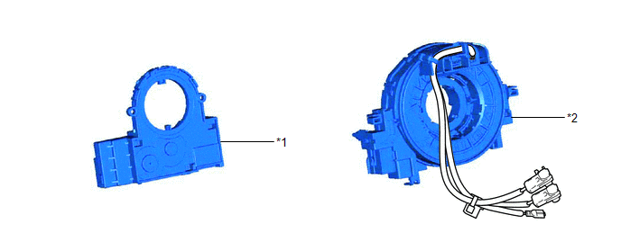
COMPONENTS
ILLUSTRATION
|
*1 | STEERING SENSOR |
*2 | SPIRAL CABLE SUB-ASSEMBLY |
Removal
REMOVAL
CAUTION / NOTICE / HINT
The necessary procedures (adjustment, calibration, initialization or registration) that must be performed after parts are removed and installed, or replaced during steering sensor removal/installation are shown below.
Necessary Procedures After Parts Removed/Installed/Replaced|
Replaced Part or Performed Procedure |
Necessary Procedure | Effect/Inoperative Function when Necessary Procedure not Performed |
Link |
|---|---|---|---|
|
Disconnect cable from negative battery terminal |
Perform steering sensor zero point calibration |
Lane tracing assist system |
|
|
Pre-collision system | |||
|
Memorize steering angle neutral point |
Parking assist monitor system |
| |
|
Panoramic view monitor system |
| ||
|
Replacement of steering sensor |
| Parking assist monitor system |
|
|
Steering angle neutral point (Initialize panoramic view monitor system) |
Panoramic view monitor system |
|
PROCEDURE
1. REMOVE SPIRAL CABLE WITH SENSOR SUB-ASSEMBLY
Click here
.gif)
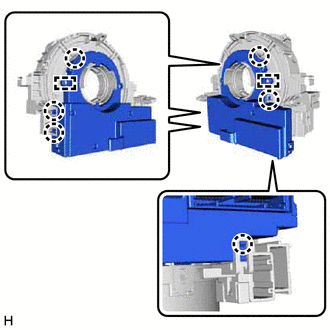
2. REMOVE STEERING SENSOR
| (a) Disengage the 6 claws and 2 pins, and remove the steering sensor from the spiral cable sub-assembly. NOTICE: Do not damage the claws and pins of the spiral cable sub-assembly. |
|
Installation
INSTALLATION
CAUTION / NOTICE / HINT
NOTICE:
A lock pin is installed to a new steering sensor. Do not remove the lock pin before the steering sensor is installed to the spiral cable sub-assembly.
PROCEDURE
1. INSPECT SPIRAL CABLE SUB-ASSEMBLY
Click here
.gif)
2. INSTALL STEERING SENSOR
| (a) Align the 2 pins and 2 guides, and engage the 6 claws to install the steering sensor to the spiral cable sub-assembly. NOTICE:
|
READ NEXT:
 Precaution
PRECAUTION PRECAUTION FOR DISCONNECTING CABLE FROM NEGATIVE BATTERY TERMINAL
NOTICE: When disconnecting the cable from the negative (-) battery terminal, initialize the following system(s) after the
Parts Location
PARTS LOCATION ILLUSTRATION
*A for 2WD
*B for AWD
*1 FRONT AXLE HUB SUB-ASSEMBLY RH
- FRONT SPEED SENSOR ROTOR RH
*2 FRONT SPEED SENSOR RH
*3 FRONT
SEE MORE:
Headlight Dimmer Switch Circuit
DESCRIPTION The steering sensor receives the following switch information:
Light control switch in DRL OFF*, tail, head or AUTO position
Dimmer switch in high, low or high flash (pass) position
*: w/ DRL OFF Switch
WIRING DIAGRAM
CAUTION / NOTICE / HINT
NOTICE: Be
Periodic maintenance
Introduction of periodic maintenance
The following tables show the normal maintenance schedule. Depending upon
weather and atmospheric conditions,
varying road surfaces, individual driving habits and vehicle usage, additional
or more frequent maintenance
may be required.
Periodic maintenan
