
Toyota Camry (XV70): Parts Location
PARTS LOCATION
ILLUSTRATION
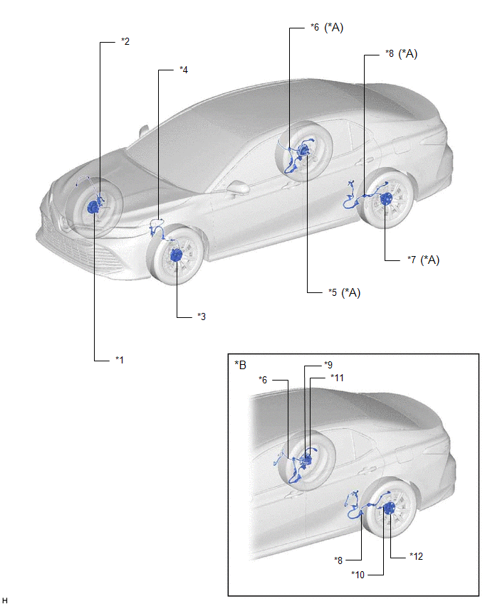
|
*A | for 2WD |
*B | for AWD |
|
*1 | FRONT AXLE HUB SUB-ASSEMBLY RH - FRONT SPEED SENSOR ROTOR RH |
*2 | FRONT SPEED SENSOR RH |
|
*3 | FRONT AXLE HUB SUB-ASSEMBLY LH - FRONT SPEED SENSOR ROTOR LH |
*4 | FRONT SPEED SENSOR LH |
|
*5 | REAR AXLE HUB AND BEARING ASSEMBLY RH - REAR SPEED SENSOR RH - REAR SPEED SENSOR ROTOR RH |
*6 | NO. 1 PARKING BRAKE WIRE ASSEMBLY - SKID CONTROL SENSOR WIRE RH |
|
*7 | REAR AXLE HUB AND BEARING ASSEMBLY LH - REAR SPEED SENSOR LH - REAR SPEED SENSOR ROTOR LH |
*8 | NO. 2 PARKING BRAKE WIRE ASSEMBLY - SKID CONTROL SENSOR WIRE LH |
|
*9 | REAR SPEED SENSOR RH |
*10 | REAR SPEED SENSOR LH |
|
*11 | REAR AXLE HUB AND BEARING ASSEMBLY RH - REAR SPEED SENSOR ROTOR RH |
*12 | REAR AXLE HUB AND BEARING ASSEMBLY LH - REAR SPEED SENSOR ROTOR LH |
ILLUSTRATION
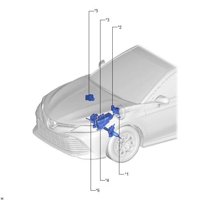
|
*1 | VACUUM WARNING SWITCH ASSEMBLY |
*2 | BRAKE MASTER CYLINDER RESERVOIR ASSEMBLY - BRAKE FLUID LEVEL WARNING SWITCH |
|
*3 | ECM |
*4 | ENGINE ROOM RELAY BLOCK AND JUNCTION BLOCK ASSEMBLY - ABS NO. 1 FUSE - ABS NO. 2 FUSE |
|
*5 | BRAKE ACTUATOR ASSEMBLY - SKID CONTROL ECU | *6 |
RACK AND PINION POWER STEERING GEAR ASSEMBLY - POWER STEERING ECU |
ILLUSTRATION
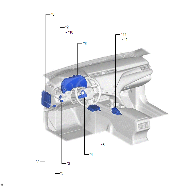
|
*1 | BRAKE HOLD SWITCH |
*2 | STOP LIGHT SWITCH ASSEMBLY |
|
*3 | VSC OFF SWITCH |
*4 | STEERING ANGLE SENSOR |
|
*5 | AIRBAG SENSOR ASSEMBLY - YAW RATE AND ACCELERATION SENSOR |
*6 | COMBINATION METER ASSEMBLY - ABS WARNING LIGHT - BRAKE SYSTEM WARNING LIGHT (RED INDICATOR) - MULTI-INFORMATION DISPLAY (TRACTION CONTROL TURNED OFF) - VSC OFF INDICATOR LIGHT - SLIP INDICATOR LIGHT - BRAKE HOLD STANDBY INDICATOR LIGHT - BRAKE HOLD OPERATED INDICATOR LIGHT |
|
*7 | INSTRUMENT PANEL JUNCTION BLOCK ASSEMBLY - ECU-IG1 NO. 2 FUSE - ECU-DCC NO. 1 FUSE - A/BAG-IG2 FUSE - STOP FUSE | *8 |
MAIN BODY ECU (MULTIPLEX NETWORK BODY ECU) |
|
*9 | DLC3 |
*10 | STOP LIGHT CONTROL RELAY |
|
*11 | ELECTRIC PARKING BRAKE SWITCH ASSEMBLY |
- | - |
READ NEXT:
 System Diagram
SYSTEM DIAGRAM
Transmitting ECU (Transmitter)
Receiving ECU Signal
Communication Method
Skid control ECU (brake actuator assembly)
Steering angle sensor
How To Proceed With Troubleshooting
CAUTION / NOTICE / HINT HINT: *: Use the Techstream. PROCEDURE
1.
VEHICLE BROUGHT TO WORKSHOP
NEXT
2.
CUSTOMER PROBLEM ANALYSIS (a) Interview
Check For Intermittent Problems
CHECK FOR INTERMITTENT PROBLEMS CHECK FOR INTERMITTENT PROBLEMS
HINT: A momentary interruption (open circuit) in the connectors and/or wire harness between the sensors and ECUs can be detected using
SEE MORE:
Pressure Control Solenoid "H" Circuit Short to Battery (P281612)
DESCRIPTION Changing gears is performed by the ECM turning the solenoid (SL1, SL2, SL3, SL4, SL5 and SL6) valves on and off.
If an open or short occurs in any of the solenoid valve circuits, the ECM controls the remaining normal solenoid valves to allow the vehicle to be driven. If all of the sole
Removal
REMOVAL CAUTION / NOTICE / HINT
The necessary procedures (adjustment, calibration, initialization, or registration) that must be performed after parts are removed and installed, or replaced during antenna cord sub-assembly removal/installation are shown below. Necessary Procedure After Parts Remov
