Toyota Camry (XV70): System Diagram
SYSTEM DIAGRAM
|
Transmitting ECU (Transmitter) |
Receiving ECU | Signal |
Communication Method |
|---|---|---|---|
|
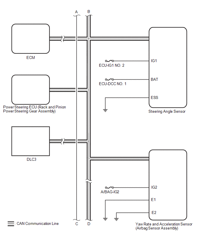
Skid control ECU (brake actuator assembly) |
Steering angle sensor | Steering angle sensor request signal |
CAN communication line |
|
Steering angle sensor |
Skid control ECU (brake actuator assembly) |
Steering angle sensor signal |
CAN communication line |
|
Skid control ECU (brake actuator assembly) |
Yaw rate and acceleration sensor (airbag sensor assembly) |
Yaw rate and acceleration request signal |
CAN communication line |
|
Yaw rate and acceleration sensor (airbag sensor assembly) |
Skid control ECU (brake actuator assembly) |
Yaw rate and acceleration signal |
CAN communication line |
|
Skid control ECU (brake actuator assembly) |
ECM |
| CAN communication line |
|
ECM | Skid control ECU (brake actuator assembly) |
| CAN communication line |
|
Skid control ECU (brake actuator assembly) |
Power steering ECU (rack and pinion power steering gear assembly) |
| CAN communication line |
|
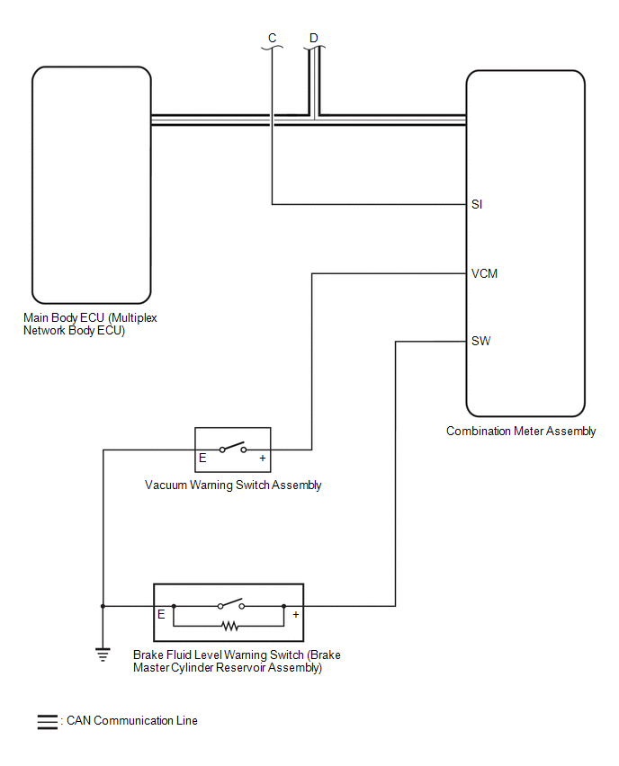
Main body ECU (multiplex network body ECU) |
Skid control ECU (brake actuator assembly) |
| CAN communication line |
|
Skid control ECU (brake actuator assembly) |
Combination meter assembly |
| CAN communication line |
|
Airbag sensor assembly |
Skid control ECU (brake actuator assembly) |
Secondary collision brake request signal |
CAN communication line |
READ NEXT:
 How To Proceed With Troubleshooting
CAUTION / NOTICE / HINT HINT: *: Use the Techstream. PROCEDURE
1.
VEHICLE BROUGHT TO WORKSHOP
NEXT
2.
CUSTOMER PROBLEM ANALYSIS (a) Interview
Check For Intermittent Problems
CHECK FOR INTERMITTENT PROBLEMS CHECK FOR INTERMITTENT PROBLEMS
HINT: A momentary interruption (open circuit) in the connectors and/or wire harness between the sensors and ECUs can be detected using
Calibration
CALIBRATION DESCRIPTION (a) Refer to the table below and then perform the necessary operation according to the part to be replaced in order to perform calibration.
Parts to be Replaced / Operati
SEE MORE:
Components
COMPONENTS ILLUSTRATION
*1 NO. 2 RADIATOR HOSE
*2 WATER INLET WITH THERMOSTAT SUB-ASSEMBLY
*3 GASKET
*4 NO. 7 WATER BY-PASS HOSE
N*m (kgf*cm, ft.*lbf): Specified torque
● Non-reusable part
Installation
INSTALLATION CAUTION / NOTICE / HINT
HINT:
Use the same procedure for the RH side and LH side.
The following procedure is for the LH side.
PROCEDURE 1. INSTALL OUTER MIRROR (for Type A)
(a) w/o Blind Spot Monitor System:
(1) Engage the 4 claws to install the outer mirror
