Toyota Camry (XV70): Installation
INSTALLATION
PROCEDURE
1. INSTALL TIMING CHAIN COVER ASSEMBLY
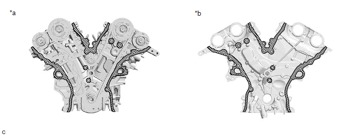
(a) Clean the contact surfaces of the engine assembly, and confirm that no oil, moisture, or other foreign matter is on the surfaces.
|
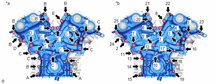
*a | Engine Assembly Side |
*b | Timing Chain Cover Assembly Side |
.png) |
Clean | - |
- |
NOTICE:
Be sure to clean the contact surfaces, especially the surfaces shown in the illustration.
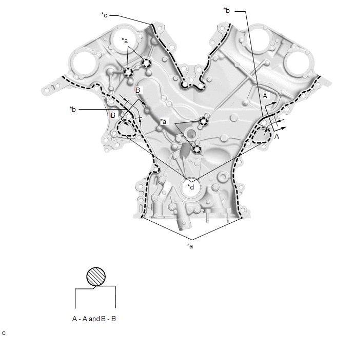
(b) Apply seal packing to the timing chain cover assembly as shown in the illustration.
|
*a | Dashed Line Area (Seal packing: Toyota Genuine Seal Packing Black, Three Bond 1207B or equivalent) |
*b | Continuous Line Area (Seal packing: Toyota Genuine Seal Packing Black, Three Bond 1207B or equivalent) |
|
*c | Alternate Long and Short Dashed Line Area (Seal packing: Toyota Genuine Seal Packing Black, Three Bond 1207B or equivalent) |
*d | Dashed Line Area (Seal packing: Toyota Genuine Seal Packing 1282B, Three Bond 1282B or equivalent) |
|
|
6.0 mm (0.236 in.) or more |
- | - |
Seal Packing:
Toyota Genuine Seal Packing Black, Three Bond 1207B or equivalent
Toyota Genuine Seal Packing 1282B, Three Bond 1282B or equivalent
NOTICE:
If there is oil on the contact surfaces, wipe them with an oil-free cloth before applying seal packing.
Seal Packing Application Chart:
|
Area | Seal Packing Diameter |
Application Position from Inside Seal Line |
|---|---|---|
|
Dashed Line Area (Seal packing: Toyota Genuine Seal Packing Black, Three Bond 1207B or equivalent) |
3.5 mm (0.138 in.) or more |
3.0 to 4.0 mm (0.118 to 0.157 in.) |
|
Continuous Line Area (Seal packing: Toyota Genuine Seal Packing Black, Three Bond 1207B or equivalent) |
6.0 mm (0.236 in.) or more |
5.0 mm (0.197 in.) |
|
Alternate Long and Short Dashed Line Area (Seal packing: Toyota Genuine Seal Packing Black, Three Bond 1207B or equivalent) |
4.5 mm (0.177 in.) or more |
3.0 to 4.0 mm (0.118 to 0.157 in.) |
|
Dashed line area (Seal packing: Toyota Genuine Seal Packing 1282B, Three Bond 1282B or equivalent) |
3.5 mm (0.138 in.) or more |
2.0 to 3.0 mm (0.0787 to 0.118 in.) |
(c) Install a new oil pump gasket to the cylinder block sub-assembly.
| (d) Align the drive rotor spline and the crankshaft as shown in the illustration. Install the timing chain cover assembly. |
|
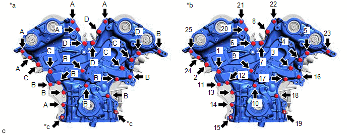
(e) w/ Stud Bolt:
(1) Install the 23 bolts and 2 nuts in the order shown in the illustration.
|
*a | Torque |
*b | Bolt and Nut Tightening Order |
|
*c | Nut |
- | - |
Bolt Length:
|
Item | Length |
|---|---|
|
(A) | 28 mm (1.10 in.) |
|
(B) | 55 mm (2.17 in.) |
|
(C) | 60 mm (2.36 in.) |
|
(D) | 40 mm (1.57 in.) |
NOTICE:
Make sure that there is no oil on the threads of the bolts.
Torque:
Bolt (A), (B)
21 N*m (214 kgf*cm, 15 ft.*lbf)
Bolt (C), (D)
43 N*m (438 kgf*cm, 32 ft.*lbf)
Nut
21 N*m (214 kgf*cm, 15 ft.*lbf)
NOTICE:
- Tighten the bolts and nuts within 10 minutes of applying seal packing.
- Do not add engine oil for at least 2 hours after installation.
- Do not start the engine for at least 2 hours after installation.
(f) w/o Stud Bolt:
(1) Install the 25 bolts in the order shown in the illustration.
|
*a | Torque |
*b | Bolt Tightening Order |
Bolt Length:
|
Item | Length |
|---|---|
|
(A) | 45 mm (1.77 in.) |
|
(B) | 28 mm (1.10 in.) |
|
(C) | 55 mm (2.17 in.) |
|
(D) | 60 mm (2.36 in.) |
|
(E) | 40 mm (1.57 in.) |
NOTICE:
Make sure that there is no oil on the threads of the bolts.
Torque:
Bolt (A), (B), (C)
21 N*m (214 kgf*cm, 15 ft.*lbf)
Bolt (D), (E)
43 N*m (438 kgf*cm, 32 ft.*lbf)
NOTICE:
- Tighten the bolts within 10 minutes of applying seal packing.
- Do not add engine oil for at least 2 hours after installation.
- Do not start the engine for at least 2 hours after installation.
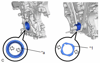
2. INSTALL TIMING CHAIN CASE OIL SEAL
Click here
.gif)
3. INSTALL OIL PAN SUB-ASSEMBLY
Click here
READ NEXT:
 Components
COMPONENTS ILLUSTRATION
*A w/ Stud Bolt
*B w/o Stud Bolt
*1 TIMING CHAIN CASE OIL SEAL
*2 TIMING CHAIN COVER ASSEMBLY
*3 OIL PUMP GASKET
- -
Removal
REMOVAL CAUTION / NOTICE / HINT
The necessary procedures (adjustment, calibration, initialization, or registration) that must be performed after parts are removed and installed, or replaced during o
Disassembly
DISASSEMBLY PROCEDURE 1. REMOVE OIL PUMP RELIEF VALVE
(a) Using a 27 mm socket wrench, remove the oil pump relief valve plug from the oil pump cover.
(b) Remove the oil pump
SEE MORE:
No Response from ID BOX (B2789)
DESCRIPTION This DTC is stored when LIN communication between the certification ECU (smart key ECU assembly) and ID code box (immobiliser code ECU) stops for 10 seconds or more.
DTC No. Detection Item
DTC Detection Condition Trouble Area
B2789 No Response from ID BOX
N
Left Front Wheel ABS Hold Solenoid Control Circuit Short to Battery (C12A512,...,C12B049)
DESCRIPTION The ABS solenoid relay and solenoid valves are built into the brake actuator assembly.
The front solenoid valve LH controls the brake fluid pressure of the front wheel cylinder LH of the vehicle.
When this DTC is stored, the fail-safe function operates and the ABS solenoid relay is t
