Toyota Camry (XV70): Rear Speed Sensor (for Awd)
Components
COMPONENTS
ILLUSTRATION
|
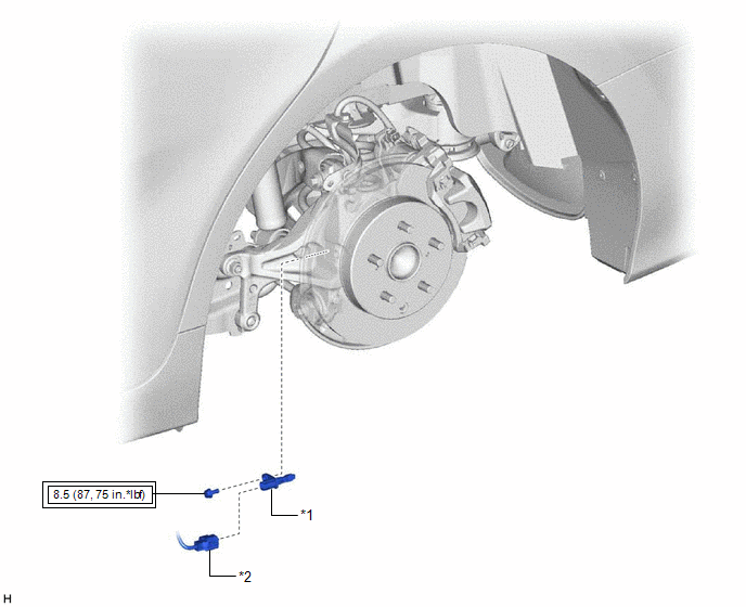
*1 | REAR SKID CONTROL SENSOR |
*2 | NO. 2 PARKING BRAKE WIRE ASSEMBLY |
.png) |
Tightening torque for "Major areas involving basic vehicle performance such as moving/turning/stopping": N*m (kgf*cm, ft.*lbf) |
- | - |
Removal
REMOVAL
CAUTION / NOTICE / HINT
HINT:
- Use the same procedure for the RH side and LH side.
- The following procedure is for the LH side.
PROCEDURE
1. REMOVE REAR WHEEL
Click here
.gif)
2. REMOVE REAR SKID CONTROL SENSOR
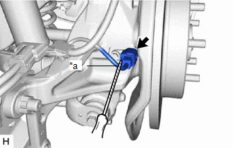
| (a) Using a screwdriver with its tip wrapped with protective tape, disconnect the No. 2 parking brake wire assembly connector from the rear skid control sensor. NOTICE:
|
|
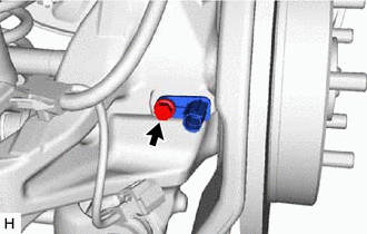
| (b) Remove the bolt and the rear skid control sensor from the rear axle carrier sub-assembly. NOTICE:
|
|
Installation
INSTALLATION
CAUTION / NOTICE / HINT
HINT:
- Use the same procedure for the RH side and LH side.
- The following procedure is for the LH side.
PROCEDURE
1. INSTALL REAR SKID CONTROL SENSOR
(a) Install the rear skid control sensor to the rear axle carrier sub-assembly with the bolt.
Torque:
8.5 N
READ NEXT:
 Steering Angle Sensor
ComponentsCOMPONENTS ILLUSTRATION
*1 STEERING SENSOR
*2 SPIRAL CABLE SUB-ASSEMBLY RemovalREMOVAL CAUTION / NOTICE / HINT
The necessary procedures (adjustment, calibration, ini
Precaution
PRECAUTION PRECAUTION FOR DISCONNECTING CABLE FROM NEGATIVE BATTERY TERMINAL
NOTICE: When disconnecting the cable from the negative (-) battery terminal, initialize the following system(s) after the
SEE MORE:
Steering Angle Sensor (C1297)
DESCRIPTION The 4WD ECU assembly determines that the vehicle is turning based on the signals sent from the steering sensor.
The steering sensor signal is sent to the 4WD ECU assembly via CAN communication.
DTC No. Detection Item
DTC Detection Condition Trouble Area
C1297 S
Initialization Switch Error (for Test Diagnosis) (C2198)
DESCRIPTION The switch circuit inside the combination meter assembly turns on and off according to the steering pad switch assembly operation.
During test mode, the tire pressure warning light blinks at 0.125 second intervals when "Set Pressure" is selected on the multi-information display, and il
