Toyota Camry (XV70): Removal
REMOVAL
CAUTION / NOTICE / HINT
HINT:
- Use the same procedure for the RH side and LH side.
- The following procedure is for the LH side.
- The front speed sensor rotor is a component of the front axle hub sub-assembly. If the front speed sensor rotor is malfunctioning, replace the front axle hub sub-assembly.
PROCEDURE
1. REMOVE FRONT WHEEL
Click here
.gif)
2. REMOVE FRONT WHEEL OPENING EXTENSION PAD
for A25A-FKS: Click here
for 2GR-FKS: Click here
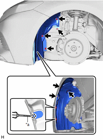
3. SEPARATE FRONT FENDER LINER
|
*a | Protective Tape |
(a) Remove the screw and 6 clips.
(b) Using a screwdriver with its tip wrapped with protective tape, disengage the 2 claws to separate the front fender liner.
4. REMOVE FRONT SPEED SENSOR
(a) Turn back the front fender liner.
| (b) Disconnect the front speed sensor connector. |
|
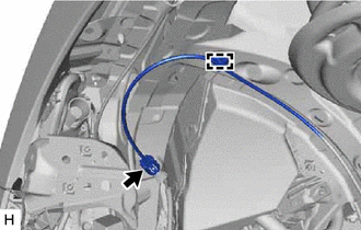
(c) Disengage the clamp.
|
(d) Remove the bolt and separate the sensor clamp. |
|
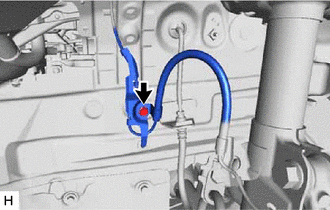
| (e) Remove the bolt and separate the front flexible hose and sensor clamp. |
|
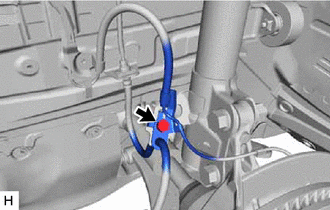
| (f) Disengage the clamp to separate the sensor clamp. |
|
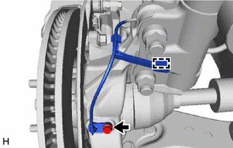
(g) Remove the bolt and front speed sensor from the steering knuckle.
NOTICE:
- Keep the tip of the front speed sensor and installation hole free of foreign matter.
- Do not rotate or apply excessive force to the front speed sensor when removing it from the steering knuckle. Rotating or applying excessive force may result in damage to the front speed sensor.
READ NEXT:
 Installation
INSTALLATION CAUTION / NOTICE / HINT
HINT:
Use the same procedure for the RH side and LH side.
The following procedure is for the LH side.
The front speed sensor rotor is a component of
Rear Speed Sensor
ComponentsCOMPONENTS ILLUSTRATION
*A w/o Electric Parking Brake System
- -
*1 PARKING BRAKE SHOE ADJUSTING HOLE PLUG
*2 REAR AXLE HUB AND BEARING ASSEMBLY
Rear Speed Sensor (for Awd)
ComponentsCOMPONENTS ILLUSTRATION
*1 REAR SKID CONTROL SENSOR
*2 NO. 2 PARKING BRAKE WIRE ASSEMBLY
Tightening torque for "Major areas involving basic vehicle perform
SEE MORE:
Components
COMPONENTS ILLUSTRATION
*1 INSTRUMENT PANEL TO PEDAL BRACKET
*2 NO. 3 INSTRUMENT PANEL TO COWL BRACE SUB-ASSEMBLY
*3 PARKING BRAKE PEDAL ASSEMBLY
*4 NO. 1 PARKING BRAKE CABLE ASSEMBLY
Tightening torque for "Major areas involving basic vehicle perf
Inspection
INSPECTION PROCEDURE 1. INSPECT FLOW SHUTTING VALVE (NO. 1 WATER BY-PASS HOSE)
(a) Measure the resistance according to the value(s) in the table below.
Standard Resistance:
Tester Connection Condition
Specified Condition
1 - 2 20°C (68°F)
22 to 28 Ω
