Toyota Camry (XV70): Disassembly
DISASSEMBLY
CAUTION / NOTICE / HINT
HINT:
- Use the same procedure for the RH side and LH side.
- The following procedure is for the LH side.
PROCEDURE
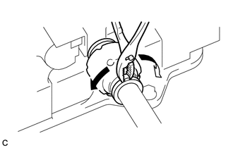
1. SEPARATE FRONT NO. 2 AXLE INBOARD JOINT BOOT CLAMP
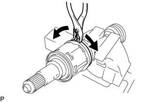
(a) Secure the drive shaft in a vise between aluminum plates.
NOTICE:
Do not overtighten the vise.
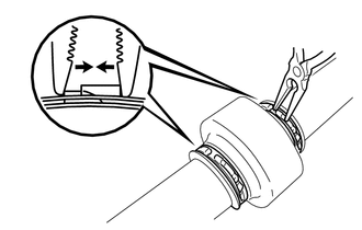
| (b) Using pliers, separate the front No. 2 axle inboard joint boot clamp as shown in the illustration. |
|
2. SEPARATE FRONT AXLE INBOARD JOINT BOOT CLAMP
HINT:
Perform the same procedure as for the front No. 2 axle inboard joint boot clamp.
3. SEPARATE FRONT AXLE INBOARD JOINT BOOT
(a) Separate the front axle inboard joint boot from the front drive inboard joint assembly.
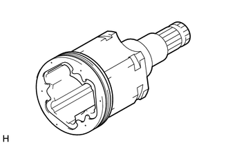
4. REMOVE FRONT DRIVE INBOARD JOINT ASSEMBLY
(a) Remove the old grease from the front drive inboard joint assembly.
| (b) Put matchmarks on the front drive inboard joint assembly and front drive outboard joint shaft assembly. NOTICE: Do not use a punch for the marks. |
|

(c) Remove the front drive inboard joint assembly from the front drive outboard joint shaft assembly.
(d) Secure the drive shaft in a vise between aluminum plates.
NOTICE:
Do not overtighten the vise.
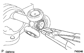
| (e) Using a snap ring expander, remove the shaft snap ring from the front drive outboard joint shaft assembly. |
|
| (f) Put matchmarks on the front drive outboard joint shaft assembly and tripod joint. NOTICE: Do not use a punch for the marks. |
|
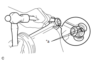
(g) Using a brass bar and a hammer, tap out the tripod joint from the front drive outboard joint shaft assembly.
NOTICE:
- Do not tap the rollers.
- Do not drop the tripod joint.
| (h) Remove the front axle inboard joint grommet from the front drive inboard joint assembly. |
|
5. REMOVE FRONT AXLE INBOARD JOINT BOOT
(a) Remove the front No. 2 axle inboard joint boot clamp, front axle inboard joint boot and front axle inboard joint boot clamp.
6. REMOVE FRONT DRIVE SHAFT DAMPER CLAMP (for LH Side)
| (a) Secure the drive shaft in a vise between aluminum plates. NOTICE: Do not overtighten the vise. |
|
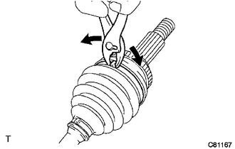
(b) Using pliers, separate the 2 front drive shaft damper clamps.
7. REMOVE FRONT DRIVE SHAFT DAMPER CLAMP (for RH Side)
(a) Secure the drive shaft in a vise between aluminum plates.
NOTICE:
Do not overtighten the vise.
| (b) Using needle-nose pliers, separate the 2 front drive shaft damper clamps. |
|
8. REMOVE FRONT DRIVE SHAFT DAMPER
(a) Remove the front drive shaft damper and 2 front drive shaft damper clamps from the front drive outboard joint shaft assembly.
9. SEPARATE FRONT NO. 2 AXLE OUTBOARD JOINT BOOT CLAMP
(a) Secure the drive shaft in a vise between aluminum plates.
NOTICE:
Do not overtighten the vise.
| (b) Using pliers, separate the front No. 2 axle outboard joint boot clamp. |
|
10. SEPARATE FRONT AXLE OUTBOARD JOINT BOOT CLAMP
HINT:
Perform the same procedure as for the front No. 2 axle outboard joint boot clamp.
11. REMOVE FRONT AXLE OUTBOARD JOINT BOOT
(a) Remove the front axle outboard joint boot clamp, front axle outboard joint boot and front No. 2 axle outboard joint boot clamp from the front drive outboard joint shaft assembly.
(b) Remove the old grease from the outboard joint.
READ NEXT:
 Inspection
INSPECTION PROCEDURE 1. INSPECT FRONT DRIVE SHAFT ASSEMBLY
(a) Check that there is no excessive play in the radial direction of the outboard joint.
(b) Check that the inboar
Reassembly
REASSEMBLY CAUTION / NOTICE / HINT
HINT:
Use the same procedure for the RH side and LH side.
The following procedure is for the LH side.
PROCEDURE 1. INSTALL FRONT AXLE OUTBOARD JOINT BO
Installation
INSTALLATION CAUTION / NOTICE / HINT
HINT:
Use the same procedure for the RH side and LH side.
The following procedure is for the LH side.
PROCEDURE 1. INSTALL FRONT DRIVE SHAFT HOLE SNA
SEE MORE:
O2 Sensor Slow Response - Rich to Lean Bank 1 Sensor 1 (P014C00-P014F00,P015A00-P015D00)
DESCRIPTION Refer to DTC P219519. Click here
HINT: Although the DTC titles say oxygen sensor, these DTCs relate to the air fuel ratio sensor.
DTC No. Detection Item
DTC Detection Condition Trouble Area
MIL Memory
Note P014C00
O2 Sensor Slow Response - Rich to
Parts Location
PARTS LOCATION ILLUSTRATION
*1 FAN WITH MOTOR ASSEMBLY - COOLING FAN MOTOR
- COOLING FAN ECU *2
ECM *3
ENGINE ROOM RELAY BLOCK AND JUNCTION BLOCK ASSEMBLY - EFI-MAIN NO. 1 RELAY
- -
