
Toyota Camry (XV70): Components
COMPONENTS
ILLUSTRATION
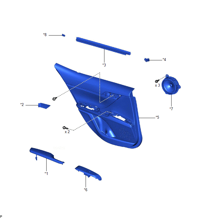
|
*1 | REAR ARMREST ASSEMBLY |
*2 | REAR DOOR ARMREST COVER SUB-ASSEMBLY |
|
*3 | REAR DOOR INNER GLASS WEATHERSTRIP |
*4 | REAR DOOR NO. 2 SERVICE HOLE COVER |
|
*5 | REAR DOOR TRIM BOARD SUB-ASSEMBLY |
*6 | REAR POWER WINDOW REGULATOR SWITCH ASSEMBLY WITH REAR DOOR UPPER ARMREST BASE PANEL |
|
*7 | REAR SPEAKER ASSEMBLY |
*8 | NO. 1 DOOR SCUFF PLATE CLAMP |
READ NEXT:
 Removal
REMOVAL CAUTION / NOTICE / HINT
HINT:
Use the same procedure for the RH side and LH side.
The following procedure is for the LH side.
PROCEDURE 1. REMOVE REAR DOOR ARMREST COVER SUB-ASSE
Inspection
INSPECTION PROCEDURE 1. INSPECT REAR SPEAKER ASSEMBLY (for 6 Speakers)
(a) With the speaker installed, check that there is no looseness or other abnormalities.
(b) Check that there is no foreign m
Installation
INSTALLATION CAUTION / NOTICE / HINT
HINT:
Use the same procedure for the RH side and LH side.
The following procedure is for the LH side.
PROCEDURE 1. INSTALL REAR SPEAKER ASSEMBLY
NO
SEE MORE:
Components
COMPONENTS ILLUSTRATION
*1 FRONT CENTER UPPER SUSPENSION BRACE SUB-ASSEMBLY
- -
Tightening torque for "Major areas involving basic vehicle performance such as moving/turning/stopping": N*m (kgf*cm, ft.*lbf)
N*m (kgf*cm, ft.*lbf): Specified torque
*T1
Cold Start Idle Control System Performance (P050A00)
MONITOR DESCRIPTION This monitor will run when the engine is started at an engine coolant temperature of -10 to 50°C (14 to 122°F). The DTC will be stored after the engine idles for 13 seconds (2 trip detection logic).
The DTC is designed to monitor the idle air control at cold start. When the e
© 2023-2026 Copyright www.tocamry.com
