Toyota Camry (XV70): Removal
REMOVAL
CAUTION / NOTICE / HINT
The necessary procedures (adjustment, calibration, initialization or registration) that must be performed after parts are removed and installed, or replaced during transmission control cable assembly removal/installation are shown below.
Necessary Procedures After Parts Removed/Installed/Replaced|
Replaced Part or Performed Procedure |
Necessary Procedure | Effect/Inoperative Function when Necessary Procedure not Performed |
Link |
|---|---|---|---|
| *1: When the ECM is replaced with a new one, reset memory is unnecessary. | |||
| Battery terminal is disconnected/reconnected |
Perform steering sensor zero point calibration |
Lane Tracing Assist System |
|
|
Pre-collision system | |||
|
Memorize steering angle neutral point |
Parking assist monitor system |
| |
|
Panoramic view monitor system |
| ||
|
Replacement of ECM | Vehicle Identification Number (VIN) registration |
MIL comes on |
|
|
ECU communication ID registration (Immobiliser system) |
Engine start function |
| |
|
Replacement of ECM (If possible, read the transaxle compensation code from the previous ECM) |
|
| for Initialization for Registration |
|
Replacement of ECM (If impossible, read the transaxle compensation code from the previous ECM) |
| ||
| Replacement of ECM |
Code registration |
|
|
PROCEDURE
1. REMOVE BATTERY
Click here .gif)
2. REMOVE ECM
Click here
3. REMOVE BATTERY CLAMP SUB-ASSEMBLY
Click here
4. REMOVE FRONT EXHAUST PIPE ASSEMBLY (TWC: Rear Catalyst)
Click here
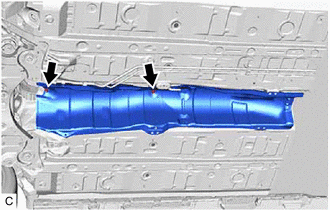
5. REMOVE FRONT LOWER NO. 1 FLOOR HEAT INSULATOR
| (a) Remove the 2 nuts and front lower No. 1 floor heat insulator from the vehicle body. |
|
6. REMOVE TRANSMISSION FLOOR SHIFT ASSEMBLY
Click here
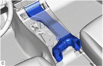
7. REMOVE NO. 1 CONSOLE BOX DUCT
| (a) Remove the No. 1 console box duct. |
|
8. REMOVE TRANSMISSION CONTROL CABLE ASSEMBLY
| (a) While disengaging the clip as shown in the illustration, disconnect the transmission control cable assembly from the transmission control shaft lever together with the clip. |
|
.png)

