Toyota Camry (XV70): Adjustment
ADJUSTMENT
PROCEDURE
1. SECURE VEHICLE
(a) Fully apply the parking brake and chock a wheel.
CAUTION:
- Make sure to apply the parking brake and chock a wheel before performing this procedure.
- If the vehicle is not secure and the shift lever is moved to N, the vehicle may suddenly move, possibly resulting in an accident or serious injury.
.png)
2. REMOVE CONSOLE BOX ASSEMBLY
Click here .gif)
3. ADJUST SHIFT LEVER POSITION
NOTICE:
Before adjusting the transmission control cable assembly, check that the park/neutral position switch assembly and shift lever are in N.
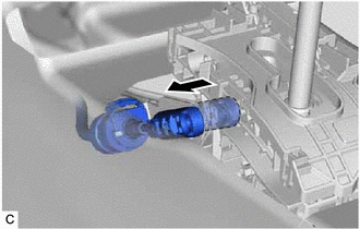
| (a) Disconnect the transmission control cable assembly from the transmission floor shift assembly. |
|
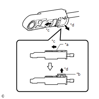
| (b) Slide the slider of the transmission control cable assembly in the direction indicated by the arrow in the illustration and pull the lock piece outward. |
|
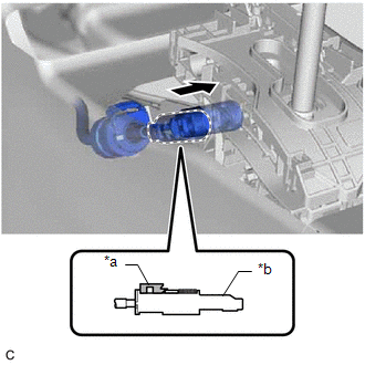
| (c) Connect the transmission control cable assembly to the transmission floor shift assembly. NOTICE:
|
|
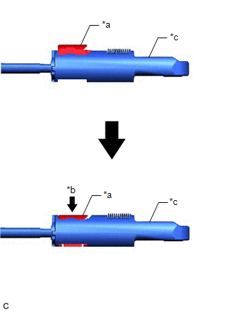
(d) Push the lock piece into the adjuster case.
|
*a | Lock Piece |
|
*b | Push in |
|
*c | Adjuster Case |
NOTICE:
- Check that the park/neutral position switch assembly and shift lever are in N.
- Securely push in the lock piece until the slider lock is engaged.
- When pushing in the lock piece of the adjuster case to lock it, remove your hand from the lever shaft.
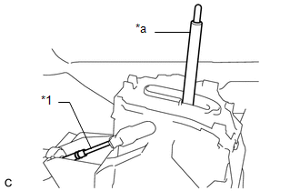
*1
Transmission Control Cable Assembly
*a
Lever Shaft
- When pushing in the lock piece of the adjuster case to lock it, do not move the lever shaft or transmission control cable assembly forward or backward.
(e) After adjusting the shift lever position, check the position and operation of the shift lever. If there is a problem, adjust the shift lever position again.
4. INSTALL CONSOLE BOX ASSEMBLY
Click here
READ NEXT:
 Installation
INSTALLATION PROCEDURE 1. INSTALL TRANSMISSION CONTROL CABLE ASSEMBLY
(a) Pass the transmission control cable assembly into the vehicle and install the transmission control cable assembly to the veh
Components
COMPONENTS ILLUSTRATION
*1 REAR ENGINE UNDER COVER LH
*2 FRONT FENDER APRON SEAL LH
*3 NO. 1 ENGINE UNDER COVER
*4 FRONT WHEEL OPENING EXTENSION PAD LH
*5
SEE MORE:
Installation
INSTALLATION PROCEDURE 1. INSTALL LEAK DETECTION PUMP SUB-ASSEMBLY
HINT: Only perform this procedure when replacement of the leak detection pump sub-assembly is necessary.
(a) Engage the 2 claws to install a new leak detection pump sub-assembly to the No. 2 charcoal canister sub-assembly.
If the vehicle becomes stuck
Carry out the following procedures if the tires spin or the vehicle
becomes stuck in mud, dirt or snow:
1. Stop the engine. Set the parking brake and shift the shift lever to P.
2. Remove the mud, snow or sand from around the front wheels.
3. Place wood, stones or some other material under the f
