Toyota Camry (XV70): Components
COMPONENTS
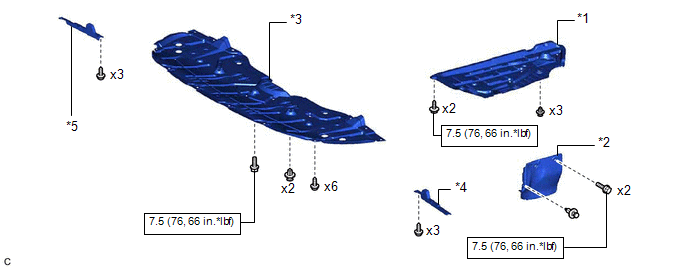
ILLUSTRATION
|
*1 | REAR ENGINE UNDER COVER LH |
*2 | FRONT FENDER APRON SEAL LH |
|
*3 | NO. 1 ENGINE UNDER COVER |
*4 | FRONT WHEEL OPENING EXTENSION PAD LH |
|
*5 | FRONT WHEEL OPENING EXTENSION PAD RH |
- | - |
.png) |
N*m (kgf*cm, ft.*lbf): Specified torque |
- | - |
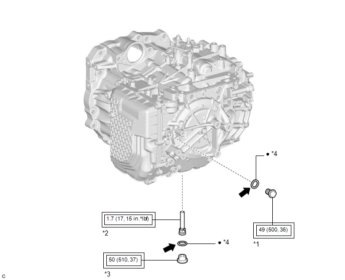
ILLUSTRATION
|
*1 | REFILL PLUG |
*2 | NO. 1 TRANSMISSION OIL FILLER TUBE |
|
*3 | OVERFLOW PLUG |
*4 | GASKET |
.png) |
Tightening torque for "Major areas involving basic vehicle performance such as moving/turning/stopping": N*m (kgf*cm, ft.*lbf) |
● | Non-reusable part |
.png) |
Toyota Genuine ATF WS |
- | - |
ILLUSTRATION

|
*1 | FRONT SUSPENSION MEMBER DYNAMIC DAMPER |
- | - |
|
|
N*m (kgf*cm, ft.*lbf): Specified torque |
- | - |
ILLUSTRATION
.png)
|
*A | for AISIN AW Made |
*B | for TMMWV Made |
|
*1 | TRANSMISSION CASE SIDE COVER |
- | - |
|
|
Tightening torque for "Major areas involving basic vehicle performance such as moving/turning/stopping": N*m (kgf*cm, ft.*lbf) |
● | Non-reusable part |
|
|
Toyota Genuine Adhesive 1324, Three Bond 1324 or equivalent |
★ | Precoated part |
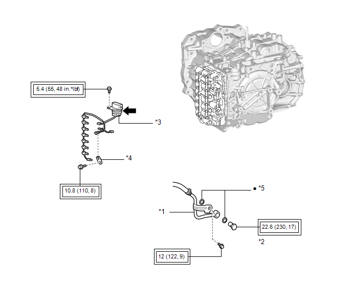
ILLUSTRATION
|
*1 | OIL COOLER UNION SUB-ASSEMBLY |
*2 | OIL COOLER UNION BOLT |
|
*3 | TRANSMISSION WIRE |
*4 | TEMPERATURE SENSOR CLAMP |
|
*5 | GASKET |
- | - |
|
|
Tightening torque for "Major areas involving basic vehicle performance such as moving/turning/stopping": N*m (kgf*cm, ft.*lbf) |
● | Non-reusable part |
|
|
Toyota Genuine ATF WS |
- | - |
READ NEXT:
 Removal
REMOVAL CAUTION / NOTICE / HINT
The necessary procedures (adjustment, calibration, initialization, or registration) that must be performed after parts are removed and installed, or replaced during t
Installation
INSTALLATION PROCEDURE 1. INSTALL TRANSMISSION WIRE
(a) Coat the O-ring of the transmission wire with Toyota Genuine ATF WS.
(b) Install the transmission wire to the automat
SEE MORE:
No Response from ID BOX (B2789)
DESCRIPTION This DTC is stored when LIN communication between the certification ECU (smart key ECU assembly) and ID code box (immobiliser code ECU) stops for 10 seconds or more.
DTC No. Detection Item
DTC Detection Condition Trouble Area
B2789 No Response from ID BOX
N
Precaution
PRECAUTION PRECAUTION FOR DISCONNECTING CABLE FROM NEGATIVE BATTERY TERMINAL
NOTICE:
After the ignition switch is turned off, the radio and display receiver assembly records various types of memory and settings. As a result, after turning the ignition switch off, make sure to wait at least 85
