Toyota Camry (XV70): Removal
REMOVAL
CAUTION / NOTICE / HINT
The necessary procedures (adjustment, calibration, initialization or registration) that must be performed after parts are removed and installed, or replaced during fuel sender gauge assembly removal/installation are shown below.
Necessary Procedures After Parts Removed/Installed/Replaced|
Replaced Part or Performed Procedure |
Necessary Procedure | Effect/Inoperative Function when Necessary Procedure not Performed |
Link |
|---|---|---|---|
|
Battery terminal is disconnected/reconnected |
Perform steering sensor zero point calibration. |
Lane Tracing Assist System |
|
|
Pre-collision System | |||
|
Memorize steering angle neutral point |
Parking Assist Monitor System |
| |
|
Panoramic View Monitor System |
|
CAUTION:
- Never perform work on fuel system components near any possible ignition sources.
.png)
- Vaporized fuel could ignite, resulting in a serious accident.
- Do not perform work on fuel system components without first disconnecting the cable from the negative (-) battery terminal.
.png)
- Sparks could cause vaporized fuel to ignite, resulting in a serious accident.
PROCEDURE
1. REMOVE FUEL SUCTION TUBE WITH PUMP AND GAUGE ASSEMBLY
Click here .gif)
2. REMOVE FUEL SENDER GAUGE ASSEMBLY
| (a) Disconnect the fuel sender gauge assembly connector. |
|
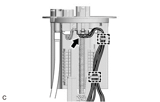
(b) Disengage the 2 clamps to disconnect the wire harness from the fuel suction plate sub-assembly.
NOTICE:
Do not damage the wire harness.
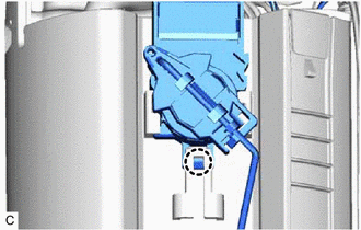
| (c) Disengage the claw to remove the fuel sender gauge assembly from the fuel suction tube with pump and gauge assembly. NOTICE: Be careful not to bend the arm of the fuel sender gauge assembly. |
|
READ NEXT:
 Inspection
INSPECTION PROCEDURE 1. INSPECT FUEL SENDER GAUGE ASSEMBLY
CAUTION: Perform the inspection in a well-ventilated area. Do not perform the inspection near an open flame.
(a) Check that the float mov
Installation
INSTALLATION PROCEDURE 1. INSTALL FUEL SENDER GAUGE ASSEMBLY
(a) Engage the claw to install the fuel sender gauge assembly to the fuel suction tube with pump and gauge assembly.
NOTICE: Be careful
Components
COMPONENTS ILLUSTRATION
*1 FUEL SENDER GAUGE ASSEMBLY
*2 FUEL SUCTION TUBE WITH PUMP AND GAUGE ASSEMBLY
SEE MORE:
Disassembly
DISASSEMBLY PROCEDURE 1. REMOVE SLIDING ROOF DRIVE GEAR SUB-ASSEMBLY
(a) Remove the bolt.
Remove in this Direction (b) Disengage the claw and guide as shown in the illustration to remove the map light bracket.
(c) Remove the 2 bolts and sliding roof drive gear sub-a
Does not Recognize Voice Commands Performed to Contact Support Center
PROCEDURE
1. CHECK COMMUNICATION BASED VOICE RECOGNITION FUNCTION
(a) While paying attention to the condition of the spoken voice command, say "Find a gas station in New York" and check that voice recognition is operating normally.
HINT:
When the voice command is recognized, the
