Toyota Camry (XV70): Operation Check
OPERATION CHECK
PERFORM BLIND SPOT MONITOR BEAM AXIS CONFIRMATION
HINT:
The blind spot monitor beam axis confirmation is performed to confirm whether the sensor beam axis is correct, and to adjust the beam axis by using a reflector.
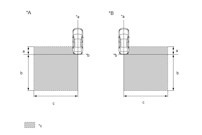
(a) When performing the blind spot monitor beam axis confirmation, move the vehicle to a place where the space shown in the illustration can be secured.
|
*A | Left Side of Vehicle |
*B | Right Side of Vehicle |
|
*a | Vehicle Center Line |
*b | Rear Bumper |
|
*c | Inspection Area |
- | - |
Standard:
|
Location | Measurement |
|---|---|
|
a | 1 m (3.28 ft.) |
|
b | 5 m (16.41 ft.) |
|
c | 6 m (19.68 ft.) |
NOTICE:
- Perform this inspection on level ground.
- Make sure that there are no metal objects around the vehicle or on the ground.
- Unload the vehicle before beginning the inspection.
- Confirm that the tire pressure is correct before beginning the inspection.
- Do not place any objects other than the reflector (such as a large metallic object) in the inspection area or allow people to enter the inspection area (W 6 m [19.68 ft.] x L 6 m [19.68 ft.] x H 4 m [13.12 ft.]) shown in the illustration.
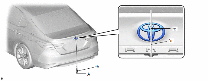
(b) Place the reflector.
(1) Hang a weight with a pointed tip from the center of the rear emblem, and mark the rear center point of the vehicle (point A) on the ground.
|
*a | String |
*b | Weight |
|
*c | Center |
- | - |
HINT:
Lightly flick the string with your fingers several times to confirm that the string is aligned with mark A.
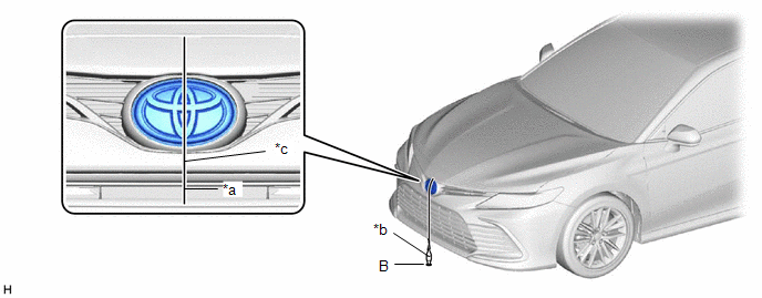
(2) Hang a weight with a pointed tip from the center of the radiator grille (or front panel) emblem, and mark the front center point of the vehicle (point B) on the ground.
|
*a | String |
*b | Weight |
|
*c | Center |
- | - |
HINT:
Lightly flick the string with your fingers several times to confirm that the string is aligned with mark B.
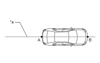
(3) Draw a vehicle center line so that it passes through mark A and B (front and rear center points).
|
*a | Vehicle Center Line |
(4) Enlarge and print out the poster shown in the illustration.
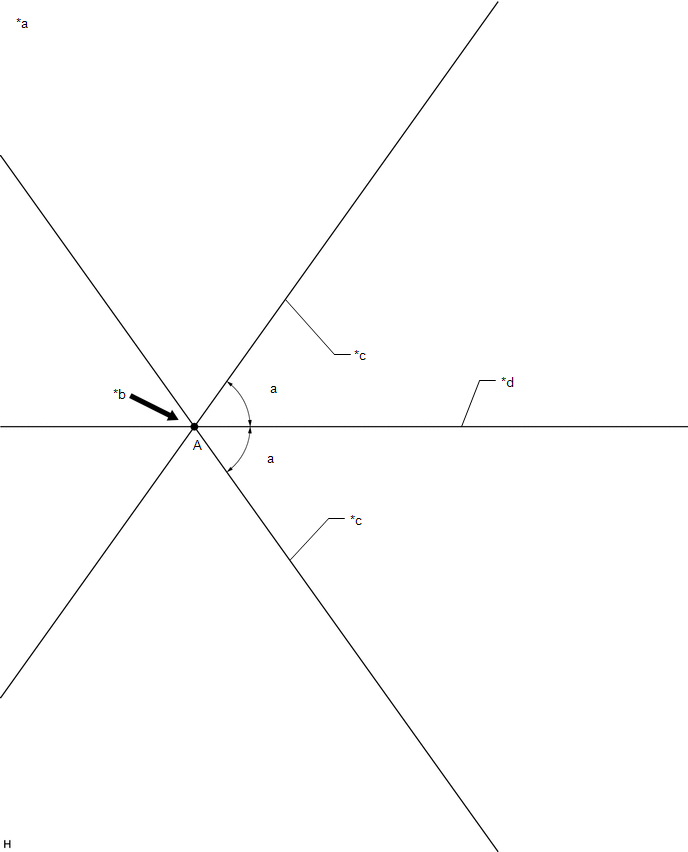
|
*a | Poster |
*b | Edge of Rear Bumper |
|
*c | Line C |
*d | Vehicle Center Line |
Standard:
|
Part | Angle |
|---|---|
|
a | 54.5 |
READ NEXT:
 Customize Parameters
CUSTOMIZE PARAMETERS CUSTOMIZE BLIND SPOT MONITOR SYSTEM
(a) Customizing with the Techstream
NOTICE:
When the customer requests a change in a function, first make sure that the function can be
Problem Symptoms Table
PROBLEM SYMPTOMS TABLE
HINT:
Use the table below to help determine the cause of problem symptoms. If multiple suspected areas are listed, the potential causes of the symptoms are listed in order
Terminals Of Ecu
TERMINALS OF ECU BLIND SPOT MONITOR SENSOR RH (MASTER)
Terminal No. (Symbol)
Wiring Color Terminal Description
Condition Specified Condition
W5-4 (OMIR) - W5-10 (BRGD)
SEE MORE:
Precaution
PRECAUTION PRECAUTION FOR DISCONNECTING CABLE FROM NEGATIVE BATTERY TERMINAL
NOTICE: When disconnecting the cable from the negative (-) battery terminal, initialize the following systems after the cable is reconnected.
System Name See Procedure
Lane Tracing Assist System
Data List / Active Test
DATA LIST / ACTIVE TEST DATA LIST NOTICE:
In the table below, the values listed under "Normal Condition" are reference values. Do not depend solely on these reference values when deciding whether a part is faulty or not.
HINT: Using the Techstream to read the Data List allows the values or state
