Toyota Camry (XV70): Oil And Oil Filter
Components
COMPONENTS
ILLUSTRATION
|
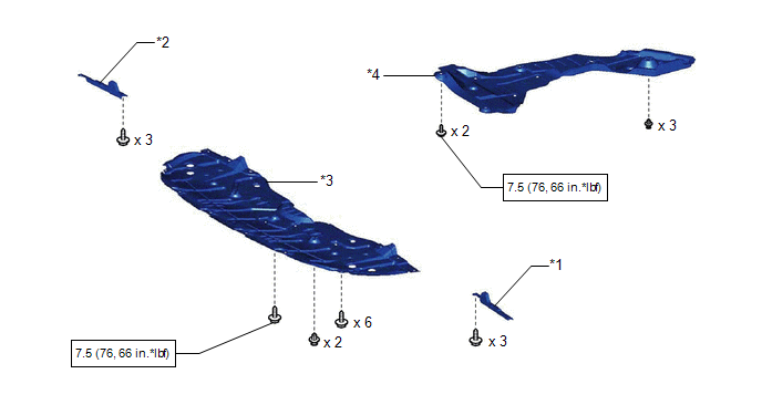
*1 | FRONT WHEEL OPENING EXTENSION PAD LH |
*2 | FRONT WHEEL OPENING EXTENSION PAD RH |
|
*3 | NO. 1 ENGINE UNDER COVER |
*4 | REAR ENGINE UNDER COVER RH |
.png) |
N*m (kgf*cm, ft.*lbf): Specified torque |
- | - |
ILLUSTRATION
|
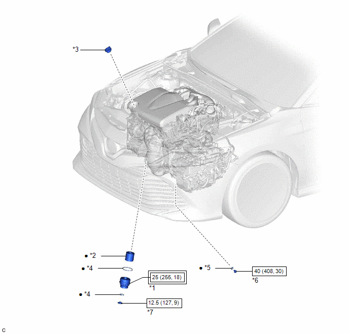
*1 | OIL FILTER CAP ASSEMBLY |
*2 | OIL FILTER ELEMENT |
|
*3 | OIL FILLER CAP SUB-ASSEMBLY |
*4 | O-RING |
|
*5 | GASKET |
*6 | OIL PAN DRAIN PLUG |
|
*7 | OIL FILTER DRAIN PLUG |
- | - |
.png) |
Tightening torque for "Major areas involving basic vehicle performance such as moving/turning/stopping": N*m (kgf*cm, ft.*lbf) |
|
N*m (kgf*cm, ft.*lbf): Specified torque |
|
● | Non-reusable part |
- | - |
Replacement
REPLACEMENT
CAUTION / NOTICE / HINT
Click here .gif)
Components
COMPONENTS
ILLUSTRATION
.png)
|
*1 | FRONT WHEEL OPENING EXTENSION PAD LH |
*2 | FRONT WHEEL OPENING EXTENSION PAD RH |
|
*3 | NO. 1 ENGINE UNDER COVER |
*4 | REAR ENGINE UNDER COVER RH |
.png) |
N*m (kgf*cm, ft.*lbf): Specified torque |
- | - |
ILLUSTRATION
.png)
|
*1 | OIL FILTER CAP ASSEMBLY |
*2 | OIL FILTER ELEMENT |
|
*3 | OIL FILLER CAP SUB-ASSEMBLY |
*4 | O-RING |
|
*5 | GASKET |
*6 | OIL PAN DRAIN PLUG |
|
*7 | OIL FILTER DRAIN PLUG |
- | - |
.png) |
Tightening torque for "Major areas involving basic vehicle performance such as moving/turning/stopping": N*m (kgf*cm, ft.*lbf) |
|
N*m (kgf*cm, ft.*lbf): Specified torque |
|
● | Non-reusable part |
- | - |
Replacement
REPLACEMENT
CAUTION / NOTICE / HINT
Click here .gif)
READ NEXT:
 Components
COMPONENTS ILLUSTRATION
*1 ENGINE OIL LEVEL SENSOR
*2 NO. 2 OIL PAN SUB-ASSEMBLY
*3 OIL STRAINER SUB-ASSEMBLY
*4 OIL STRAINER GASKET
N*m (kgf*cm, f
Removal
REMOVAL CAUTION / NOTICE / HINT
The necessary procedures (adjustment, calibration, initialization, or registration) that must be performed after parts are removed and installed, or replaced during e
SEE MORE:
Panoramic moon roof
Use the overhead switches to operate the panoramic moon roof
and electronic sunshade.
Opening and closing the electronic sunshade
Opens the electronic sunshade
Slide and hold the switch
backward. The electronic sunshade
will fully open automatically.*
Closes the electronic sunshade
Suggestion function
Displays suggestions to the driver in the following situations. To select
a response to a displayed suggestion, use the meter control switches.
The suggestion function can be turned on/off.
■ Suggestion to turn off the headlights
If the headlights are left on for a certain amount of time aft
