Toyota Camry (XV70): Components
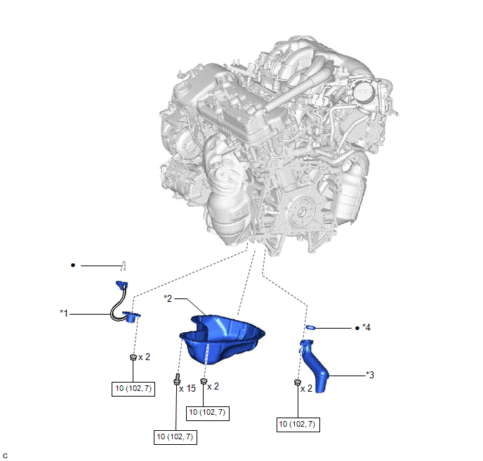
COMPONENTS
ILLUSTRATION
|
*1 | ENGINE OIL LEVEL SENSOR |
*2 | NO. 2 OIL PAN SUB-ASSEMBLY |
|
*3 | OIL STRAINER SUB-ASSEMBLY |
*4 | OIL STRAINER GASKET |
.png) |
N*m (kgf*cm, ft.*lbf): Specified torque |
● | Non-reusable part |
READ NEXT:
 Removal
REMOVAL CAUTION / NOTICE / HINT
The necessary procedures (adjustment, calibration, initialization, or registration) that must be performed after parts are removed and installed, or replaced during e
Inspection
INSPECTION PROCEDURE 1. INSPECT ENGINE OIL LEVEL SENSOR
(a) Measure the resistance according to the value(s) in the table below.
Standard Resistance:
Tester Connection Condition
Installation
INSTALLATION PROCEDURE 1. INSTALL ENGINE OIL LEVEL SENSOR
(a) Install the engine oil level sensor to the oil pan sub-assembly with the 2 nuts.
Torque: 10 N·m {102 kgf·cm, 7 ft·lbf} (b) Install
SEE MORE:
Installation
INSTALLATION CAUTION / NOTICE / HINT
NOTICE:
Immediately after installing the brake pads, the braking performance may be reduced. Always perform a road test in a safe place while paying attention to the surroundings.
After replacing the rear disc brake pads, always perform a road test to
Installation
INSTALLATION PROCEDURE 1. INSTALL TRANSMISSION VALVE BODY ASSEMBLY
(a) Coat 2 new transaxle case gaskets with Toyota Genuine ATF WS and install them to the automatic transaxle case sub-assembly.
(b) Coat a new transaxle case gasket with Toyota Genuine ATF WS and install it to the counter drive g
© 2023-2026 Copyright www.tocamry.com
