Toyota Camry (XV70): Removal
REMOVAL
CAUTION / NOTICE / HINT
The necessary procedures (adjustment, calibration, initialization, or registration) that must be performed after parts are removed and installed, or replaced during engine oil level sensor removal/installation are shown below.
Necessary Procedure After Parts Removed/Installed/Replaced|
Replaced Part or Performed Procedure |
Necessary Procedure | Effect/Inoperative Function when Necessary Procedure not Performed |
Link |
|---|---|---|---|
| *1: When the ECM is replaced with a new one, reset memory is unnecessary. | |||
| Battery terminal is disconnected/reconnected |
Perform steering sensor zero point calibration |
Lane Tracing Assist System |
|
|
Pre-collision System | |||
|
Memorize steering angle neutral point |
Parking Assist Monitor System |
| |
|
Panoramic view monitor system |
| ||
|
Replacement of ECM | Vehicle Identification Number (VIN) registration |
MIL comes on |
|
|
ECU communication ID registration (Immobiliser system) |
Engine start function |
| |
| Inspection After Repair |
|
|
|
Replacement of automatic transaxle assembly |
|
|
|
|
Replacement of ECM (If possible, read the transaxle compensation code from the previous ECM) |
| ||
| Replacement of ECM (If impossible, read the transaxle compensation code from the previous ECM) |
| ||
| Replacement of ECM |
Code registration |
|
|
|
Replacement of automatic transaxle fluid |
ATF thermal degradation estimate reset |
The value of the Data List item "ATF Thermal Degradation Estimate" is not estimated correctly. |
|
|
Suspension, tires, etc. (The vehicle height changes because of suspension or tire replacement) |
Rear television camera assembly optical axis (Back camera position setting) |
Parking assist monitor system |
|
|
Replacement of front bumper assembly |
Front television camera view adjustment |
Panoramic view monitor system |
|
|
Suspension, tires, etc. (The vehicle height changes because of suspension or tire replacement) |
| ||
| Front wheel alignment adjustment |
|
|
|
PROCEDURE
1. INSTALL ENGINE ASSEMBLY TO ENGINE STAND
Click here
.gif)
2. REMOVE NO. 2 OIL PAN SUB-ASSEMBLY
Click here
3. REMOVE OIL STRAINER SUB-ASSEMBLY
Click here
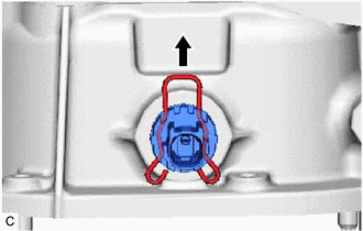
4. REMOVE ENGINE OIL LEVEL SENSOR
| (a) Remove the clip from the engine oil level sensor. |
|
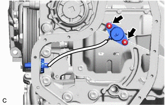
| (b) Remove the 2 nuts and engine oil level sensor from the oil pan sub-assembly. |
|
READ NEXT:
 Inspection
INSPECTION PROCEDURE 1. INSPECT ENGINE OIL LEVEL SENSOR
(a) Measure the resistance according to the value(s) in the table below.
Standard Resistance:
Tester Connection Condition
Installation
INSTALLATION PROCEDURE 1. INSTALL ENGINE OIL LEVEL SENSOR
(a) Install the engine oil level sensor to the oil pan sub-assembly with the 2 nuts.
Torque: 10 N·m {102 kgf·cm, 7 ft·lbf} (b) Install
Components
COMPONENTS ILLUSTRATION
*1 ENGINE OIL LEVEL SENSOR
*2 NO. 2 OIL PAN SUB-ASSEMBLY
*3 OIL STRAINER SUB-ASSEMBLY
*4 OIL STRAINER GASKET
N*m (kgf*cm, f
SEE MORE:
How To Proceed With Troubleshooting
CAUTION / NOTICE / HINT
HINT:
Before performing troubleshooting for the front radar sensor system, perform troubleshooting for the pre-collision system.
Click here
*: Use the Techstream.
PROCEDURE
1. VEHICLE BROUGHT TO WORKSHOP
NEXT
2.
Fuel Rail Pressure Sensor (Low) Circuit Short to Ground (P107A11)
DESCRIPTION
The fuel pressure sensor (for low pressure side) replaces the fuel pressure with electrical signals and outputs them to the ECM. The ECM controls the optimal fuel pressure for the operation conditions to reduce the fuel pump power consumption and improve fuel economy.
DTC No.
