Toyota Camry (XV70): Adjustment
ADJUSTMENT
PROCEDURE
1. STEERING WHEEL OFF CENTER ADJUSTMENT PROCEDURE
(a) Inspect steering wheel off center.
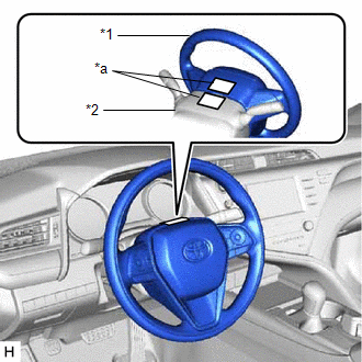
(1) Turn the steering wheel assembly to the center position.
| (2) Apply masking tape to the top center of the steering wheel assembly and upper steering column cover. |
|
(3) Drive the vehicle in a straight line for 100 m (328 ft.) at a constant speed of 56 km/h (35 mph), while holding the steering wheel assembly to maintain the course.
| (4) Draw a line on the masking tape as shown in the illustration. |
|
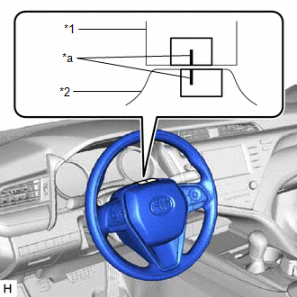
(5) Turn the steering wheel assembly to the center position.
| (6) Draw a new line on the masking tape on the steering wheel assembly as shown in the illustration. |
|
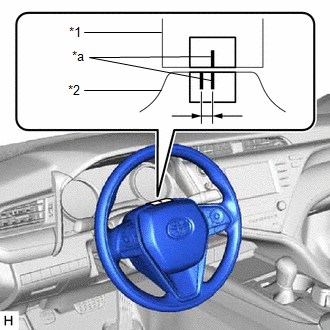
(7) Measure the distance between the 2 lines on the masking tape on the steering wheel assembly.
(8) Convert the measured distance to the steering angle.
HINT:
- Measured distance of 1 mm (0.0394 in.) = Steering angle of approximately 1 degree
- Make a note of the steering angle.
(b) Adjust the steering angle.
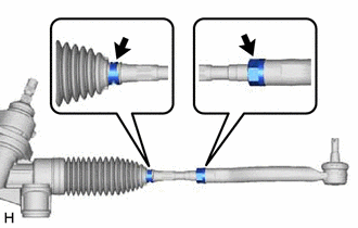
| (1) Put matchmarks on the tie rod assemblies LH and RH and steering rack end sub-assembly respectively. |
|
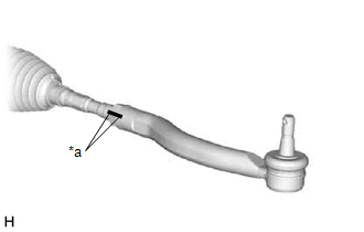
(2) Using a paper gauge, measure the thread length of the steering rack end sub-assemblies.
HINT:
- Measure both RH and LH sides.
- Make a note of the measured values.
| (3) Remove the steering rack boot clips from the RH and LH steering rack boots. |
|
(4) Loosen the RH and LH lock nuts.
(5) Turn the RH and LH steering rack end sub-assemblies by the same amount (but in different directions) according to the measured steering angle.
HINT:
One 360 degree turn of a steering rack end (1.5 mm (0.0591 in.) horizontal movement) equals 9.2 degrees of steering angle.
(6) Tighten the RH and LH lock nuts to the specified torque.
Torque:
88 N
READ NEXT:
 Components
COMPONENTS ILLUSTRATION
*1 STEERING WHEEL ASSEMBLY
- -
Tightening torque for "Major areas involving basic vehicle performance such as moving/turning/stopping"
Removal
REMOVAL CAUTION / NOTICE / HINT
The necessary procedures (adjustment, calibration, initialization, or registration) that must be performed after parts are removed and installed, or replaced during
SEE MORE:
Removal
REMOVAL CAUTION / NOTICE / HINT
NOTICE:
Immediately after installing the brake pads, the braking performance may be reduced. Always perform a road test in a safe place while paying attention to the surroundings.
After replacing the front disc brake pads, the brake pedal may feel soft due
Components
COMPONENTS ILLUSTRATION
*1 NO. 2 PARKING BRAKE WIRE ASSEMBLY
*2 REAR AXLE HUB AND BEARING ASSEMBLY
*3 REAR DISC
*4 REAR DISC BRAKE CALIPER ASSEMBLY
*5 REAR FLEXIBLE HOSE
*6 REAR DISC BRAKE DUST COVER SUB-ASSEMBLY
Tightening torqu
