Toyota Camry (XV70): Removal
REMOVAL
CAUTION / NOTICE / HINT
The necessary procedures (adjustment, calibration, initialization, or registration) that must be performed after parts are removed and installed, or replaced during steering wheel assembly removal/installation are shown below.
Necessary Procedures After Parts Removed/Installed/Replaced|
Replaced Part or Performed Procedure |
Necessary Procedure | Effect/Inoperative Function when Necessary Procedure not Performed |
Link |
|---|---|---|---|
|
Disconnect cable from negative battery terminal |
Perform steering sensor zero point calibration |
Lane tracing assist system |
|
|
Pre-collision system | |||
|
Memorize steering angle neutral point |
Parking assist monitor system |
| |
|
Panoramic view monitor system |
|
NOTICE:
- Do not remove/install the spiral cable with sensor sub-assembly with the battery connected and the ignition switch ON.
- Do not rotate the spiral cable with sensor sub-assembly without the steering wheel assembly installed, with the battery connected and the ignition switch ON.
- Ensure that the steering wheel assembly is installed and aligned straight when inspecting the steering sensor.
PROCEDURE
1. ALIGN FRONT WHEELS FACING STRAIGHT AHEAD
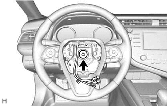
2. REMOVE HORN BUTTON ASSEMBLY
Click here
.gif)
3. REMOVE STEERING WHEEL ASSEMBLY
(a) Disconnect each connector.
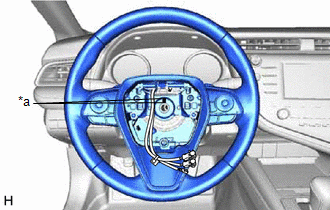
| (b) Using a 10 mm hexagon socket wrench, remove the steering wheel assembly set bolt. |
|
| (c) Put matchmarks on the steering wheel assembly and steering main shaft. |
|
(d) Temporarily install the steering wheel assembly set bolt.
NOTICE:
Do not overtighten the steering wheel assembly set bolt.
| (e) Using SST, separate the steering wheel assembly. SST: 09950-50013 09951-05010 09952-05010 09953-05020 09954-05031 09957-04010 SST: 09950-60010 09951-00330 NOTICE: Apply a small amount of grease to the threads and tip of SST (09953-05020) before use. |
|
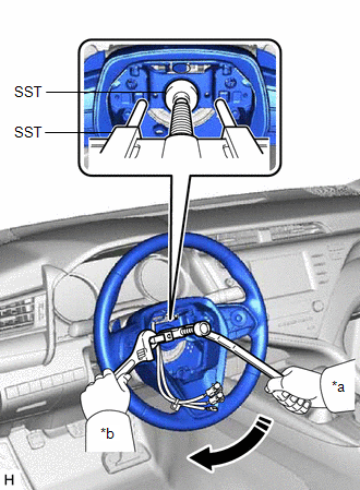
(f) Remove the steering wheel assembly set bolt and steering wheel assembly.
4. REMOVE STEERING PAD SWITCH ASSEMBLY
Click here
5. REMOVE SHIFT PADDLE SWITCH (TRANSMISSION SHIFT SWITCH ASSEMBLY) (w/ Shift Paddle Switch)
for UB80E: Click here
for UB80F: Click here
for UA80E: Click here
6. REMOVE NO. 1 SWITCH WIRE (w/ Shift Paddle Switch)
for UB80E: Click here
for UB80F: Click here
for UA80E: Click here
READ NEXT:
 Installation
INSTALLATION CAUTION / NOTICE / HINT
NOTICE:
Do not remove/install the spiral cable with sensor sub-assembly with the battery connected and the ignition switch ON.
Do not rotate the sp
SEE MORE:
Installation
INSTALLATION PROCEDURE 1. INSTALL BRAKE BOOSTER GASKET
(a) Install a new brake booster gasket to the brake booster assembly. 2. INSTALL BRAKE BOOSTER ASSEMBLY
(a) Temporarily install the brake booster assembly to the vehicle body.
NOTICE: Do not apply excessive force to the brake lines. (b) Te
Right Front Wheel Speed Sensor Circuit Short to Ground or Open (C050614)
DESCRIPTION Refer to DTC C050612 Click here
DTC No. Detection Item
DTC Detection Condition Trouble Area
C050614 Right Front Wheel Speed Sensor Circuit Short to Ground or Open
A short or open circuit is detected in the speed sensor signal circuit for 0.12 seconds or
