Toyota Camry (XV70): Removal
REMOVAL
CAUTION / NOTICE / HINT
The necessary procedures (adjustment, calibration, initialization, or registration) that must be performed after parts are removed and installed, or replaced during central gateway ECU (network gateway ECU) removal/installation are shown below.
Necessary Procedures After Parts Removed/Installed/Replaced|
Replaced Part or Performed Procedure |
Necessary Procedure | Effect/Inoperative Function when Necessary Procedure not Performed |
Link |
|---|---|---|---|
| *: w/ Smart Key System | |||
| Battery terminal is disconnected/reconnected |
Perform steering sensor zero point calibration |
Lane Tracing Assist System |
|
|
Pre-collision system | |||
|
Memorize steering angle neutral point |
Parking assist monitor system |
| |
|
Panoramic view monitor system |
| ||
|
Replacement of certification ECU (smart key ECU assembly)* |
Code registration (Smart key System (for Start Function) |
|
|
|
Replacement of clearance warning ECU assembly |
|
|
|
CAUTION:
Some of these service operations affect the SRS airbag system. Read the precautionary notices concerning the SRS airbag system before servicing.
Click here .gif)
PROCEDURE
1. REMOVE LOWER NO. 2 INSTRUMENT PANEL AIRBAG ASSEMBLY
Click here
2. REMOVE LOWER INSTRUMENT PANEL SUB-ASSEMBLY
Click here
3. REMOVE ECU INTEGRATION BOX RH (w/ Smart Key System)
(a) Disconnect each connector.
| (b) Disengage the 2 clamps. |
|
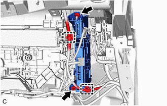
(c) Remove the bolt, nut and ECU integration box RH.
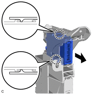
4. REMOVE CENTRAL GATEWAY ECU (NETWORK GATEWAY ECU) (w/ Smart Key System)
| (a) Disengage the 2 claws and remove the central gateway ECU (network gateway ECU). NOTICE:
|
|
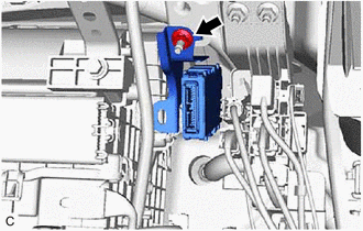
5. REMOVE CENTRAL GATEWAY ECU (NETWORK GATEWAY ECU) (w/o Smart Key System)
| (a) Disconnect the central gateway ECU (network gateway ECU) connector. |
|
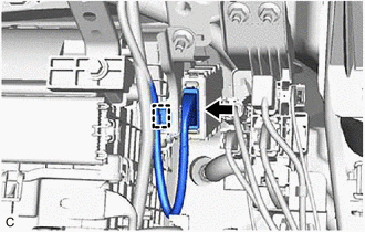
(b) Disengage the clamp.
|
(c) Remove the nut and central gateway ECU (network gateway ECU). |
|
READ NEXT:
 Installation
INSTALLATION CAUTION / NOTICE / HINT PROCEDURE
1. INSTALL CENTRAL GATEWAY ECU (NETWORK GATEWAY ECU) (w/o Smart Key System)
(a) Engage the clamp. (b) Connect the central gateway ECU (network gatewa
SEE MORE:
GPS Antenna Connection Malfunction(short) (B15C0,B15C1)
DESCRIPTION These DTCs are stored when a malfunction occurs in the navigation antenna assembly.
DTC No. Detection Item
DTC Detection Condition Trouble Area
B15C0 GPS Antenna Connection Malfunction(short)
Navigation antenna malfunction
Navigation antenna asse
If your vehicle overheats
The following may indicate that your vehicle is overheating.
The needle of the engine coolant temperature gauge enters the red zone
or a loss of engine power is experienced. (For
example, the vehicle speed does not increase.)
"Engine Coolant Temp High Stop in a Safe Place See Owner's
Ma
