Toyota Camry (XV70): Parts Location
PARTS LOCATION
ILLUSTRATION
|
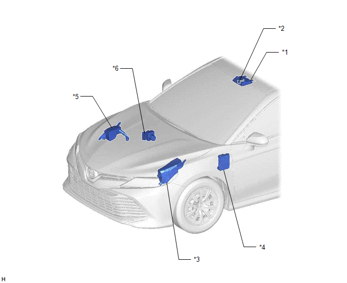
*1 | ROOF CONSOLE BOX SUB-ASSEMBLY |
*2 | TELEPHONE MICROPHONE ASSEMBLY |
|
*3 | ENGINE ROOM RELAY BLOCK AND JUNCTION BLOCK ASSEMBLY - TV FUSE | *4 |
INSTRUMENT PANEL JUNCTION BLOCK ASSEMBLY - ECU-ACC FUSE - ECU-DCC NO. 2 FUSE - ECU-IG1 NO. 4 FUSE - ECU-IG2 NO. 3 FUSE (w/ Manual (SOS) Switch) - DCM FUSE (w/ Manual (SOS) Switch) - PANEL FUSE - METER-IG2 FUSE - ECU-B NO. 2 FUSE |
|
*5 | NO. 2 ENGINE ROOM RELAY BLOCK AND JUNCTION BLOCK ASSEMBLY - AMP NO. 1 FUSE - AMP NO. 2 FUSE |
*6 | SKID CONTROL ECU (BRAKE ACTUATOR ASSEMBLY) |
ILLUSTRATION
|
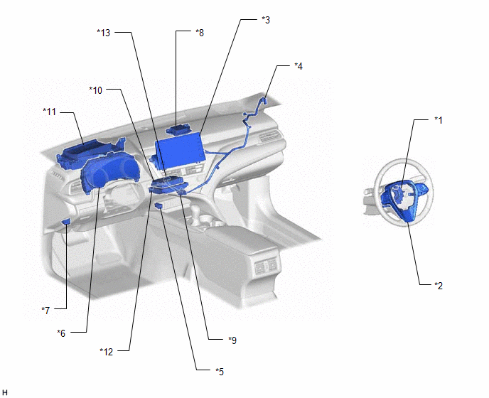
*1 | SPIRAL CABLE SUB-ASSEMBLY |
*2 | STEERING PAD SWITCH ASSEMBLY |
|
*3 | RADIO AND DISPLAY RECEIVER ASSEMBLY |
*4 | ANTENNA CORD SUB-ASSEMBLY (for Front Side) |
|
*5 | NO. 1 STEREO JACK ADAPTER ASSEMBLY |
*6 | COMBINATION METER ASSEMBLY |
|
*7 | DLC3 |
*8 | NAVIGATION ANTENNA ASSEMBLY - GPS |
| *9 |
ANTENNA CORD SUB-ASSEMBLY (for Navigation Antenna) |
*10 | DCM (TELEMATICS TRANSCEIVER) (w/ Manual (SOS) Switch) |
|
*11 | HEADUP DISPLAY (METER MIRROR SUB-ASSEMBLY) (w/ Headup Display System) |
*12 | NAVIGATION ECU |
|
*13 | NO. 1 NAVIGATION WIRE |
- | - |
ILLUSTRATION
.png)
|
*1 | FRONT NO. 1 SPEAKER ASSEMBLY LH |
*2 | FRONT NO. 1 SPEAKER ASSEMBLY RH |
|
*3 | FRONT NO. 2 SPEAKER ASSEMBLY LH |
*4 | FRONT NO. 2 SPEAKER ASSEMBLY RH |
|
*5 | RADIO SETTING CONDENSER |
*6 | FRONT NO. 3 SPEAKER ASSEMBLY LH |
|
*7 | FRONT NO. 3 SPEAKER ASSEMBLY RH |
*8 | REAR SPEAKER ASSEMBLY LH |
|
*9 | REAR SPEAKER ASSEMBLY RH |
*10 | REAR STEREO COMPONENT SPEAKER ASSEMBLY |
|
*11 | STEREO COMPONENT AMPLIFIER ASSEMBLY |
- | - |
ILLUSTRATION
.png)
|
*1 | WINDOW GLASS ANTENNA WIRE |
*2 | NO. 1 AMPLIFIER ANTENNA ASSEMBLY |
|
*3 | NO. 2 AMPLIFIER ANTENNA ASSEMBLY |
*4 | NO. 2 ANTENNA CORD SUB-ASSEMBLY |
|
*5 | ROOF ANTENNA ASSEMBLY (w/ SXM Function) - SiriusXM | *6 |
NO. 5 ANTENNA CORD SUB-ASSEMBLY (w/ SXM Function) |
|
*7 | ANTENNA CORD SUB-ASSEMBLY (for Rear Side) |
*8 | - FM Sub |
|
*9 | - FM Main - AM |
- | - |
READ NEXT:
 System Diagram
SYSTEM DIAGRAM
w/ Manual (SOS) Switch
w/o Manual (SOS) Switch
System Description
SYSTEM DESCRIPTION NAVIGATION SYSTEM OUTLINE (a) Vehicle position tracking methods
It is essential that the navigation system correctly tracks the current vehicle position and displays it on the map
How To Proceed With Troubleshooting
CAUTION / NOTICE / HINT
HINT:
Use the following procedure to troubleshoot the navigation system.
*: Use the Techstream.
PROCEDURE
1. VEHICLE BROUGHT TO WORKSHOP
SEE MORE:
Inspection
INSPECTION PROCEDURE 1. INSPECT BRAKE VACUUM CHECK VALVE ASSEMBLY
(a) Check that there is ventilation from the booster side to the engine side, and no ventilation from the engine side to the booster side of the brake vacuum check valve assembly.
If the result is not as specified, replace th
Installation
INSTALLATION PROCEDURE 1. INSTALL VACUUM PUMP ASSEMBLY
(a) Clean the vacuum pump assembly installation bolt holes in the camshaft housing sub-assembly and cylinder head sub-assembly.
(b) When using a new vacuum pump assembly: (1) Apply engine oil to the 2 O-rings which are installed to a new vac
