Toyota Camry (XV70): System Diagram
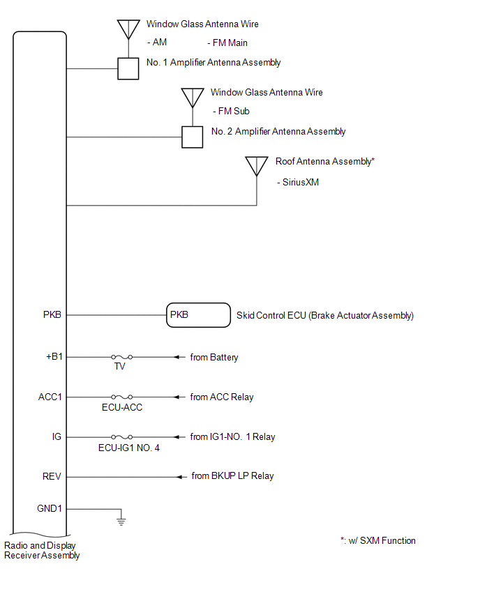
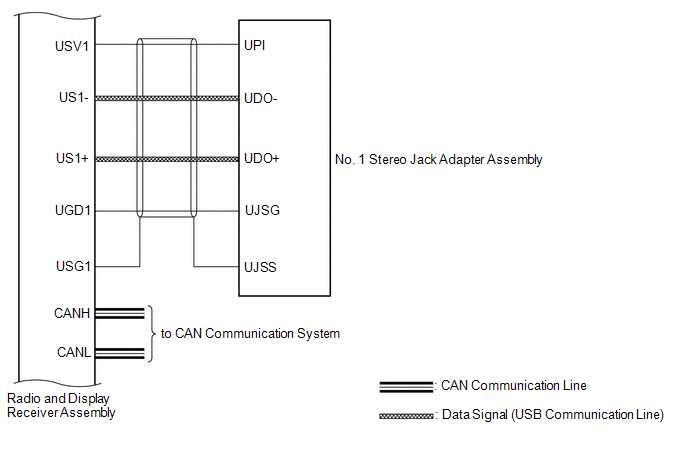
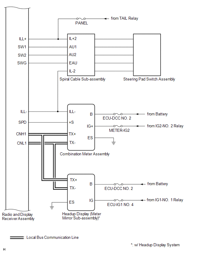
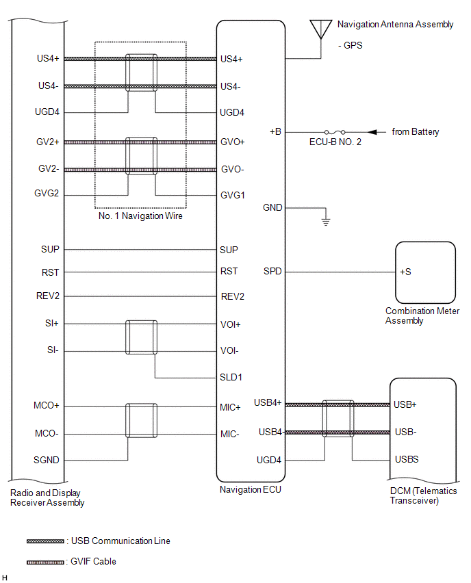
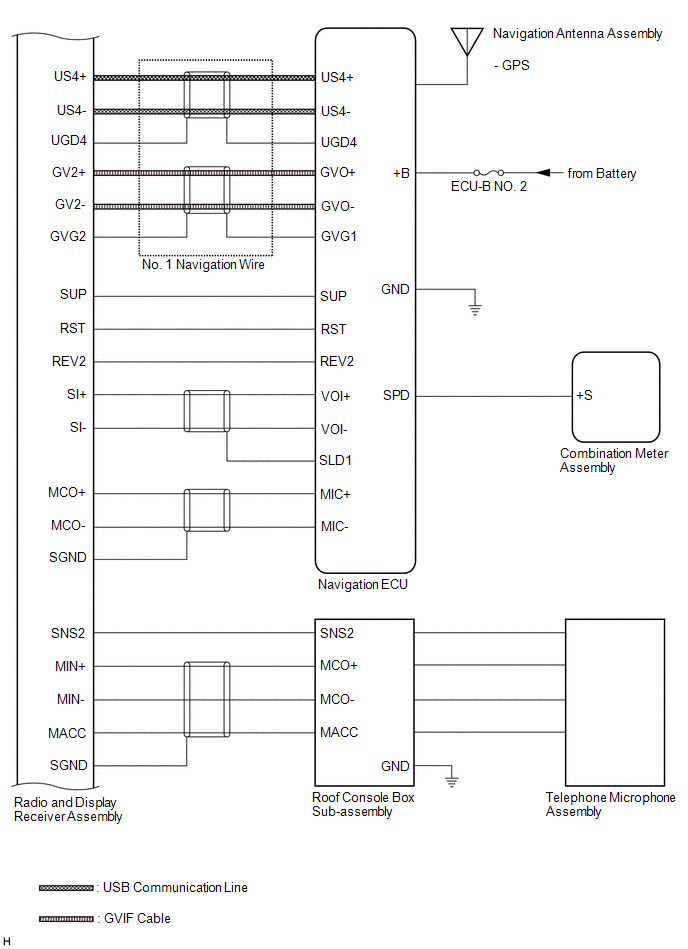
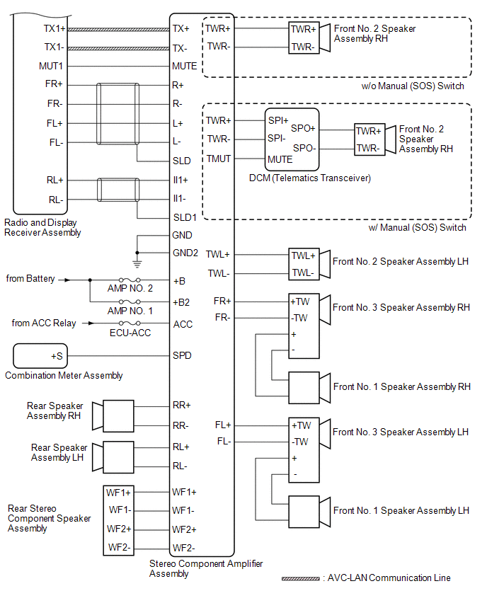
SYSTEM DIAGRAM
 w/ Manual (SOS) Switch
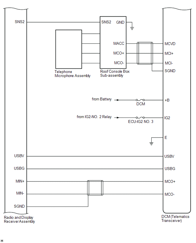 w/o Manual (SOS) Switch
READ NEXT:
 System Description
SYSTEM DESCRIPTION NAVIGATION SYSTEM OUTLINE (a) Vehicle position tracking methods
It is essential that the navigation system correctly tracks the current vehicle position and displays it on the map
How To Proceed With Troubleshooting
CAUTION / NOTICE / HINT
HINT:
Use the following procedure to troubleshoot the navigation system.
*: Use the Techstream.
PROCEDURE
1. VEHICLE BROUGHT TO WORKSHOP
Operation Check
OPERATION CHECK CHECK NAVIGATION SYSTEM NORMAL CONDITION
(a) If the cause of a symptom is any of the following, the corresponding symptom is normal; it is not due to a malfunction.
Symptom A
SEE MORE:
Open in Outer Mirror Indicator(Master) (C1AB4)
DESCRIPTION This DTC is stored when the blind spot monitor sensor RH detects an open in the outer rear view mirror indicator RH.
DTC No. Detection Item
DTC Detection Condition Trouble Area
C1AB4 Open in Outer Mirror Indicator(Master) Both of the following conditions are me
Installation
INSTALLATION PROCEDURE 1. INSTALL ENGINE OIL PRESSURE SWITCH ASSEMBLY
(a) Apply adhesive to 2 or 3 threads of the engine oil pressure switch assembly.
Adhesive: Toyota Genuine Adhesive 1344, Three Bond 1344 or equivalent
NOTICE:
Do not apply adhesive to the oil inlet port of the e
© 2023-2026 Copyright www.tocamry.com
