Toyota Camry (XV70): Installation
INSTALLATION
PROCEDURE
1. INSTALL FLOW SHUTTING VALVE (WATER BY-PASS HOSE ASSEMBLY)
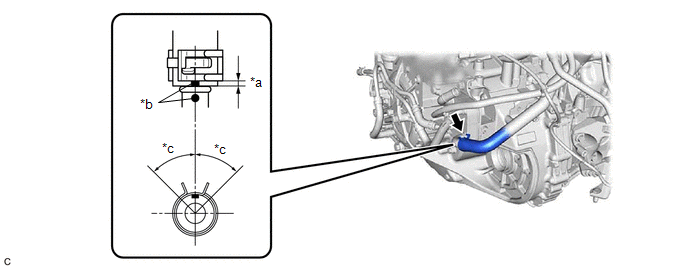
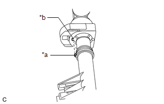
(a) Connect the flow shutting valve (water by-pass hose assembly) to the transmission oil cooler and slide the clip to secure it.
|
*a | 2 to 7 mm (0.0787 to 0.276 in.) |
*b | Paint Mark |
|
*c | 45° (Tabs of Clip Installation Area) |
- | - |
NOTICE:
- Make sure to slide the flow shutting valve (water by-pass hose assembly) until it contacts the hose stopper of the transmission oil cooler.
- Make sure to align the paint mark of the flow shutting valve (water by-pass hose assembly) with the paint mark of the transmission oil cooler.
- Make sure that the tabs of the clip are within the area shown in the illustration.
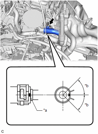
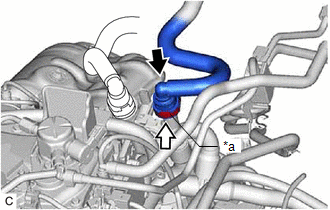
| (b) Connect the flow shutting valve (water by-pass hose assembly) to the water by-pass outlet sub-assembly and slide the clip to secure it. NOTICE:
|
|
(c) Install the water hose clamp bracket with the 2 bolts.
Torque:
13 N·m {133 kgf·cm, 10 ft·lbf}
(d) Engage the 2 clamps to connect the wire harness.
(e) Connect the flow shutting valve (water by-pass hose assembly) with the bolt.
Torque:
19 N·m {194 kgf·cm, 14 ft·lbf}
(f) Connect the No. 2 water by-pass pipe sub-assembly with the bolt.
Torque:
19 N·m {194 kgf·cm, 14 ft·lbf}
(g) Connect the inlet heater hose connector to the flow shutting valve (water by-pass hose assembly).
NOTICE:
Check that there is no damage or foreign matter on the connecting parts of the water lines.
| (1) Align the protrusions of the inlet heater hose connector with the cutouts in the flow shutting valve (water by-pass hose assembly) and push them together until the inlet heater hose connector makes a "click" sound. |
|
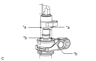
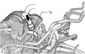
(2) Push in the retainer.
|
*a | Retainer |
.png) |
Push |
.png) |
Push in |
(3) Check that the flow shutting valve (water by-pass hose assembly) and inlet heater hose connector are securely connected by pulling on them.
(h) Connect the outlet heater hose connector to the No. 2 water by-pass pipe sub-assembly.
NOTICE:
Check that there is no damage or foreign matter on the connecting parts of the water lines.
| (1) Align the protrusion of the No. 2 water by-pass pipe sub-assembly with the cutout in the outlet heater hose connector and push them together until the outlet heater hose connector makes a "click" sound. |
|
(2) Push in the retainer.
|
*a | Retainer |
|
|
Push |
|
|
Push in |
(3) Check that the No. 2 water by-pass pipe sub-assembly and outlet heater hose connector are securely connected by pulling on them.
(i) Engage the clamp to connect the engine wire harness to the water hose clamp bracket.
(j) Connect the 3 connectors.
(k) Engage the clamp to connect the vacuum hose to the engine wire harness.
2. INSTALL FLOW SHUTTING VALVE (NO. 1 WATER BY-PASS HOSE)
Click here
.gif)
READ NEXT:
 Components
COMPONENTS ILLUSTRATION
*1 FRONT WHEEL OPENING EXTENSION PAD LH
*2 FRONT WHEEL OPENING EXTENSION PAD RH
*3 NO. 1 ENGINE UNDER COVER
*4 NO. 2 ENGINE UNDER COVER AS
On-vehicle Inspection
ON-VEHICLE INSPECTION CAUTION / NOTICE / HINT
CAUTION: Do not remove the radiator cap sub-assembly while the engine and radiator assembly are still hot. Pressurized, hot engine coolant and steam may
SEE MORE:
Rear Power Window LH Auto Up / Down Function does not Operate with Rear Power Window Switch LH
DESCRIPTION If the manual up and down functions operate normally but the auto up and down functions do not, the power window control system may be in fail-safe mode.
If power window initialization has not been performed, the auto up and down functions will not operate.
Click here WIRING DIAG
Removal
REMOVAL PROCEDURE 1. REMOVE NO. 1 INSTRUMENT PANEL UNDER COVER SUB-ASSEMBLY
Click here
2. REMOVE STOP LIGHT SWITCH ASSEMBLY
(a) Disconnect the connector.
(b) Turn the stop light switch assembly counterclockwise and remove it.
Remove in thi
