Toyota Camry (XV70): Inspection
INSPECTION
PROCEDURE
1. INSPECT FRONT NO. 2 SPEAKER ASSEMBLY (for 6 Speakers)
(a) With the speaker installed, check that there is no looseness or other abnormalities.
(b) Check that there is no foreign matter in the speaker, no tears on the speaker cone or other abnormalities.
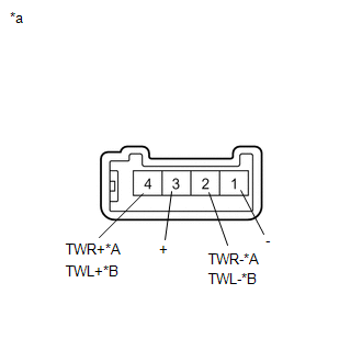
| (c) Measure the resistance of the speaker. Standard Resistance: for RH
If the result is not as specified, replace the speaker. |
|
(d) When there is a possibility that either the right or left speaker is malfunctioning, interchange the speakers and perform an inspection. If the malfunction disappears after interchanging the speakers, replace the malfunctioning speaker.
HINT:
Connect all connectors to the speakers when performing an inspection. If the result is not as specified, replace the speaker.
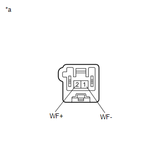
2. INSPECT FRONT NO. 2 SPEAKER ASSEMBLY (for 9 Speakers)
(a) With the speaker installed, check that there is no looseness or other abnormalities.
(b) Check that there is no foreign matter in the speaker, no tears on the speaker cone or other abnormalities.
| (c) Measure the resistance of the speaker. Standard Resistance:
If the result is not as specified, replace the speaker. |
|
READ NEXT:
 Installation
INSTALLATION CAUTION / NOTICE / HINT
HINT:
Use the same procedure for the RH side and LH side.
The following procedure is for the LH side.
PROCEDURE 1. INSTALL FRONT NO. 2 SPEAKER ASSEMB
Microphone
ComponentsCOMPONENTS ILLUSTRATION
*A for Normal Roof
*B except Normal Roof
*1 ROOF CONSOLE BOX ASSEMBLY
*2 TELEPHONE MICROPHONE ASSEMBLY
*3 ROOF CONSOLE
SEE MORE:
Inspection
INSPECTION PROCEDURE 1. INSPECT BRAKE CYLINDER AND PISTON
(a) Check the rear disc brake cylinder bore and rear disc brake piston for rust and scoring. If necessary, replace the rear disc brake cylinder and rear disc brake piston.
2. INSPECT PAD LINING THICKNESS
(a) Using a ruler, measure t
Installation
INSTALLATION PROCEDURE 1. INSTALL TIMING CHAIN CASE OIL SEAL
(a) Apply MP grease to the lip of a new timing chain case oil seal.
*a Oil Seal Protrusion Height
(b) Using SST and a hammer, tap in the timing chain case oil seal until its surface is flus
