Toyota Camry (XV70): Microphone
Components
COMPONENTS
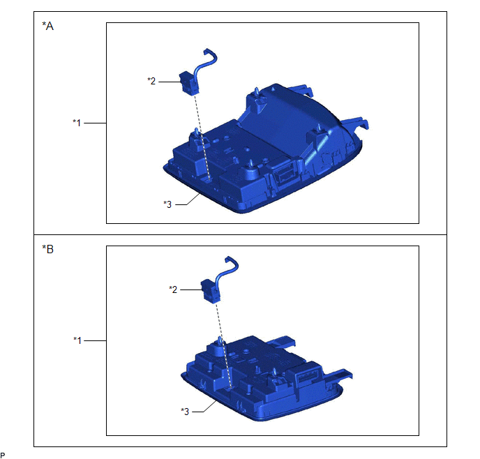
ILLUSTRATION
|
*A | for Normal Roof |
*B | except Normal Roof |
|
*1 | ROOF CONSOLE BOX ASSEMBLY |
*2 | TELEPHONE MICROPHONE ASSEMBLY |
|
*3 | ROOF CONSOLE BOX SUB-ASSEMBLY |
- | - |
Removal
REMOVAL
PROCEDURE
1. REMOVE ROOF CONSOLE BOX ASSEMBLY
Click here
.gif)
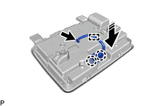
2. REMOVE TELEPHONE MICROPHONE ASSEMBLY
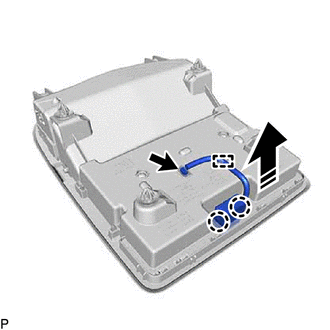
(a) for Normal Roof:
(1) Disconnect the connector.
 |
Remove in this Direction |
(2) Disengage the clamp.
(3) Disengage the 2 claws and remove the telephone microphone assembly from the roof console box sub-assembly as shown in the illustration.
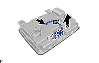
(b) except Normal Roof:
(1) Disconnect the connector.
|
|
Remove in this Direction |
(2) Disengage the clamp.
(3) Disengage the 2 claws and remove the telephone microphone assembly from the roof console box sub-assembly as shown in the illustration.
Installation
INSTALLATION
PROCEDURE
1. INSTALL TELEPHONE MICROPHONE ASSEMBLY
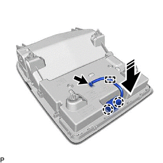
(a) for Normal Roof:
(1) Engage the 2 claws to install the telephone microphone assembly to the roof console box sub-assembly as shown in the illustration.
.png) |
Install in this Direction |
(2) Engage the clamp.
(3) Connect the connector.
(b) except Normal Roof:
(1) Engage the 2 claws to install the telephone microphone assembly to the roof console box sub-assembly as shown in the illustration.
|
|
Install in this Direction |
(2) Engage the clamp.
(3) Connect the connector.
2. INSTALL ROOF CONSOLE BOX ASSEMBLY
Click here .gif)
READ NEXT:
 Components
COMPONENTS ILLUSTRATION
*A for Fold Down Seat Type
- -
*1 REAR SEAT CUSHION ASSEMBLY
*2 REAR SEAT CUSHION LOCK HOOK
*3 REAR SIDE SEATBACK ASSEMBLY LH
On-vehicle Inspection
ON-VEHICLE INSPECTION PROCEDURE
1. INSPECT RADIO SETTING CONDENSER (for High Mounted Stop Light) (a) With the radio setting condenser installed, check that there is no looseness or other abnormaliti
SEE MORE:
Installation
INSTALLATION PROCEDURE 1. INSTALL ENGINE WATER PUMP ASSEMBLY
(a) Install a new water pump gasket and the engine water pump assembly with the 15 bolts.
Torque: Bolt (A) : 43 N·m {438 kgf·cm, 32 ft·lbf} Bolt (B) :
21 N·m {214 kgf·cm, 15 ft·lbf} Bolt (C) : 11 N·m {112 kgf·cm, 8
Installation
INSTALLATION PROCEDURE 1. INSTALL NO. 1 FUEL TANK CUSHION
(a) Install 2 new No. 1 fuel tank cushions to the fuel tank assembly. 2. INSTALL NO. 6 FUEL TANK CUSHION
(a) Install a new No. 6 fuel tank cushion to the fuel tank assembly. 3. INSTALL FUEL TANK MAIN TUBE SUB-ASSEMBLY
(a) Engage the cla
