Toyota Camry (XV70): On-vehicle Inspection
ON-VEHICLE INSPECTION
PROCEDURE
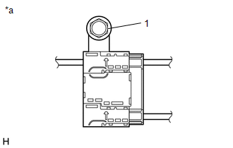
1. INSPECT RADIO SETTING CONDENSER (for High Mounted Stop Light)
(a) With the radio setting condenser installed, check that there is no looseness or other abnormalities.
| (b) Measure the resistance of the radio setting condenser according to the value(s) in the table below. Standard Resistance:
|
|
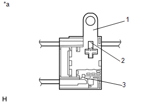
(c) Remove the bolt.
(d) Disengage the clamp and disconnect the radio setting condenser with wire harness from the vehicle body.
| (e) Measure the resistance and voltage of the radio setting condenser according to the value(s) in the table below. Standard Resistance:
Standard Voltage:
|
|
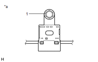
2. INSPECT RADIO SETTING CONDENSER (for Window Defogger)
(a) With the radio setting condenser installed, check that there is no looseness or other abnormalities.
| (b) Measure the resistance of the radio setting condenser according to the value(s) in the table below. Standard Resistance:
|
|
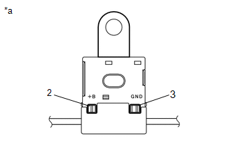
(c) Remove the bolt.
(d) Disengage the 2 clamps and disconnect the radio setting condenser with wire harness from the vehicle body.
| (e) Measure the resistance and voltage of the radio setting condenser according to the value(s) in the table below. Standard Resistance:
Standard Voltage:
|
|
READ NEXT:
 Removal
REMOVAL CAUTION / NOTICE / HINT
The necessary procedures (adjustment, calibration, initialization or registration) that must be performed after parts are removed and installed, or replaced during ra
Pillar Speaker
ComponentsCOMPONENTS ILLUSTRATION
*1 FRONT DOOR OPENING TRIM WEATHERSTRIP
*2 FRONT NO. 3 SPEAKER ASSEMBLY
*3 FRONT PILLAR GARNISH
*4 CLIP
● Non-re
SEE MORE:
Components
COMPONENTS ILLUSTRATION
*1 FUEL PUMP ASSEMBLY
*2 FUEL PUMP PROTECTOR
*3 NO. 1 FUEL PIPE SUB-ASSEMBLY
*4 NO. 2 FUEL TUBE SUB-ASSEMBLY
*5 FUEL PUMP LIFTER ASSEMBLY
*6 FUEL PUMP LIFTER GUIDE
*7 FUEL PUMP SPACER GASKET
*8 FUEL TUB
Sun visors
To set the visor in the forward
position, flip it down.
To set the visor in the side position,
flip down, unhook, and
swing it to the side.
To use the side extender, place
the visor in the side position,
then slide it backward.
Vanity mirrors
Slide the cover to open.
Vehicl
