Toyota Camry (XV70): Pillar Speaker
Components
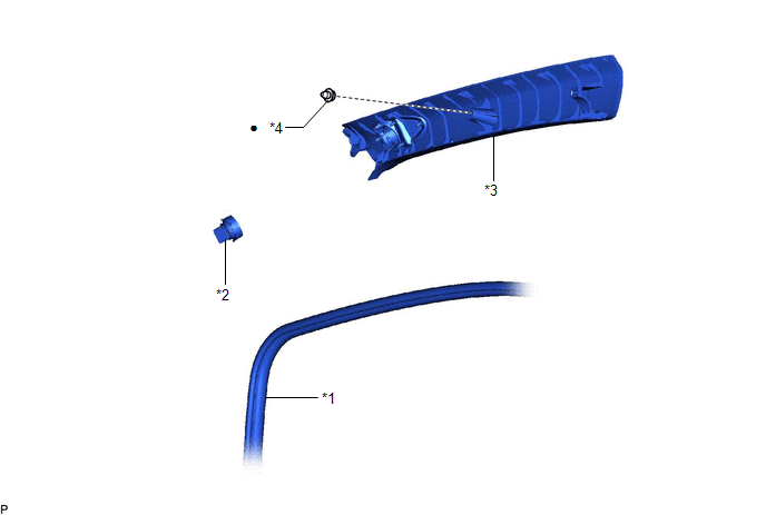
COMPONENTS
ILLUSTRATION
|
*1 | FRONT DOOR OPENING TRIM WEATHERSTRIP |
*2 | FRONT NO. 3 SPEAKER ASSEMBLY |
|
*3 | FRONT PILLAR GARNISH |
*4 | CLIP |
|
● | Non-reusable part |
- | - |
Removal
REMOVAL
CAUTION / NOTICE / HINT
HINT:
- Use the same procedure for the RH side and LH side.
- The following procedure is for the LH side.
PROCEDURE
1. DISCONNECT FRONT DOOR OPENING TRIM WEATHERSTRIP
Click here .gif)
2. REMOVE FRONT PILLAR GARNISH
Click here
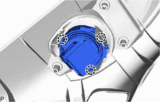
3. REMOVE FRONT NO. 3 SPEAKER ASSEMBLY
NOTICE:
Do not touch the speaker cone.
| (a) Disengage the 3 claws to remove the front No. 3 speaker assembly. |
|
Inspection
INSPECTION
PROCEDURE
1. INSPECT FRONT NO. 3 SPEAKER ASSEMBLY
(a) With the speaker installed, check that there is no looseness or other abnormalities.
(b) Check that there is no foreign matter in the speaker, no tears on the speaker cone or other abnormalities.
(c) When there is a possibility that either the right or left speaker is malfunctioning, interchange the speakers and perform an inspection. If the malfunction disappears after interchanging the speakers, replace the malfunctioning speaker.
HINT:
Connect all connectors to the speakers when performing an inspection. If the result is not as specified, replace the speaker.
Installation
INSTALLATION
CAUTION / NOTICE / HINT
HINT:
- Use the same procedure for the RH side and LH side.
- The following procedure is for the LH side.
PROCEDURE
1. INSTALL FRONT NO. 3 SPEAKER ASSEMBLY
NOTICE:
Do not touch the speaker cone.
(a) Engage the 3 claws to install the front No. 3 speaker assembly.
2. INSTALL FRONT PILLAR GARNISH
Click here
.gif)
3. INSTALL FRONT DOOR OPENING TRIM WEATHERSTRIP
Click here
READ NEXT:
 Components
COMPONENTS ILLUSTRATION
*A w/o Navigation Antenna
*B w/ Navigation Antenna
*1 ANTENNA CORD SUB-ASSEMBLY
*2 INSTRUMENT PANEL SAFETY PAD SUB-ASSEMBLY
*3 N
Removal
REMOVAL CAUTION / NOTICE / HINT
The necessary procedures (adjustment, calibration, initialization, or registration) that must be performed after parts are removed and installed, or replaced during a
SEE MORE:
If your vehicle needs
to be towed
If towing is necessary, we recommend having your vehicle
towed by your Toyota dealer or commercial towing service,
using a wheel-lift type truck or flatbed truck.
Use a safety chain system for all towing, and abide by all state/
provincial and local laws.
2WD models: If towing your vehicle wi
Parts Location
PARTS LOCATION ILLUSTRATION
*A w/o Smart Key System
*B for Toyota Entune Remote Connect Compatible Type
*1 DOOR CONTROL SWITCH ASSEMBLY
*2 UNLOCK WARNING SWITCH ASSEMBLY
*3 DLC3
*4 MAIN BODY ECU (MULTIPLEX NETWORK BODY ECU)
*5 INSTRUMENT PANEL
