Toyota Camry (XV70): Components
COMPONENTS
ILLUSTRATION
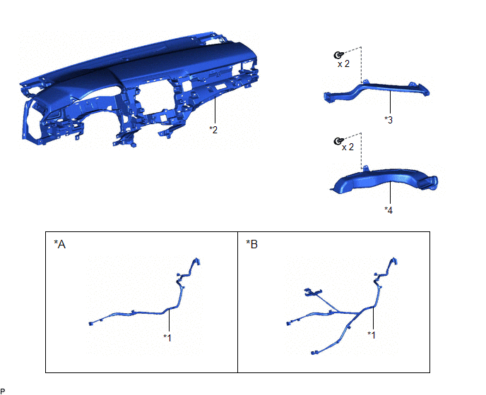
|
*A | w/o Navigation Antenna |
*B | w/ Navigation Antenna |
|
*1 | ANTENNA CORD SUB-ASSEMBLY |
*2 | INSTRUMENT PANEL SAFETY PAD SUB-ASSEMBLY |
|
*3 | NO. 2 SIDE DEFROSTER NOZZLE DUCT |
*4 | NO. 3 HEATER TO REGISTER DUCT SUB-ASSEMBLY |
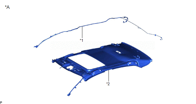
ILLUSTRATION
|
*A | for Normal Roof |
- | - |
|
*1 | NO. 2 ANTENNA CORD SUB-ASSEMBLY |
*2 | ROOF HEADLINING ASSEMBLY |
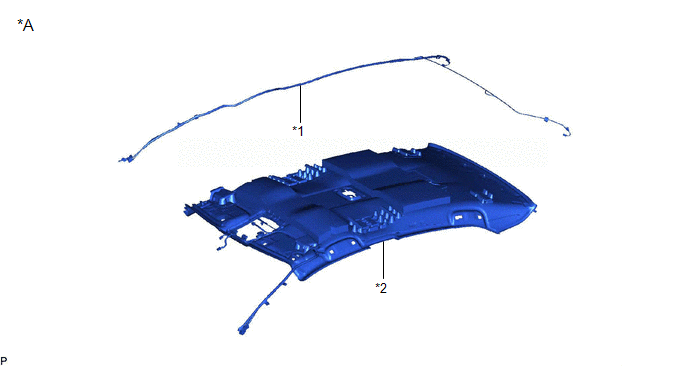
ILLUSTRATION
|
*A | for Moon Roof |
- | - |
|
*1 | NO. 2 ANTENNA CORD SUB-ASSEMBLY |
*2 | ROOF HEADLINING ASSEMBLY |
ILLUSTRATION
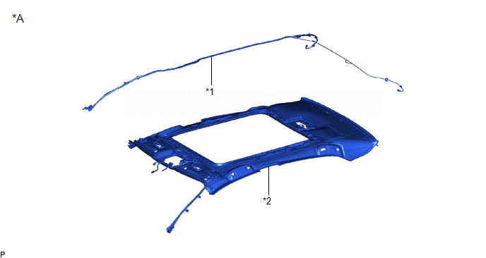
|
*A | for Panoramic Moon Roof |
- | - |
|
*1 | NO. 2 ANTENNA CORD SUB-ASSEMBLY |
*2 | ROOF HEADLINING ASSEMBLY |
ILLUSTRATION
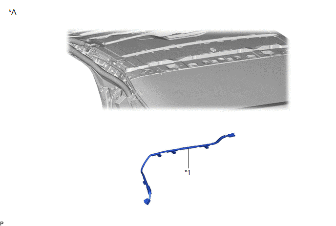
|
*A | w/ Manual (SOS) Switch |
- | - |
|
*1 | NO. 5 ANTENNA CORD SUB-ASSEMBLY |
- | - |
READ NEXT:
 Removal
REMOVAL CAUTION / NOTICE / HINT
The necessary procedures (adjustment, calibration, initialization, or registration) that must be performed after parts are removed and installed, or replaced during a
Installation
INSTALLATION PROCEDURE 1. INSTALL NO. 5 ANTENNA CORD SUB-ASSEMBLY (w/ Manual (SOS) Switch)
(a) Engage the 5 clamps to install the No. 5 antenna cord sub-assembly.
(b) Connect the connector. 2. INS
SEE MORE:
Evaporative Emission System Incorrect Purge Flow Actuator Stuck On (P04417E,P04417F,P04419C)
DTC SUMMARY
DTC No. Detection Item
DTC Detection Condition Trouble Area
MIL Memory
Note P04417E
Evaporative Emission System Incorrect Purge Flow Actuator Stuck On
Leak detection pump creates negative pressure (vacuum) in EVAP system and EVAP system pressure
Removal
REMOVAL CAUTION / NOTICE / HINT
The necessary procedures (adjustment, calibration, initialization, or registration) that must be performed after parts are removed and installed, or replaced during back window glass sub-assembly removal/installation are shown below. Necessary Procedures After Part
© 2023-2026 Copyright www.tocamry.com
