Toyota Camry (XV70): Installation
INSTALLATION
CAUTION / NOTICE / HINT
HINT:
- Use the same procedure for the RH side and LH side.
- The following procedure is for the LH side.
PROCEDURE
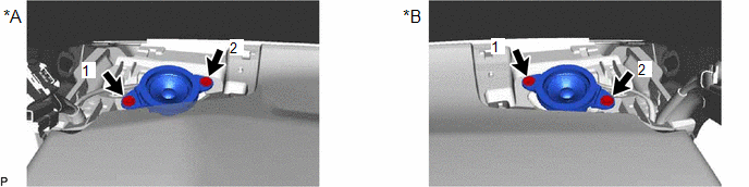
1. INSTALL FRONT NO. 2 SPEAKER ASSEMBLY
NOTICE:
Do not touch the speaker cone.
(a) Connect the connector.
(b) Install the front No. 2 speaker assembly with the 2 screws.
|
*A | for LH Side |
*B | for RH Side |
HINT:
Install the screws in the order shown in the illustration.
2. INSTALL NO. 1 INSTRUMENT PANEL SPEAKER PANEL
Click here
.gif)
3. INSTALL FRONT PILLAR GARNISH
Click here
4. INSTALL FRONT DOOR OPENING TRIM WEATHERSTRIP
Click here
READ NEXT:
 Microphone
ComponentsCOMPONENTS ILLUSTRATION
*A for Normal Roof
*B except Normal Roof
*1 ROOF CONSOLE BOX ASSEMBLY
*2 TELEPHONE MICROPHONE ASSEMBLY
*3 ROOF CONSOLE
Components
COMPONENTS ILLUSTRATION
*A for Fold Down Seat Type
- -
*1 REAR SEAT CUSHION ASSEMBLY
*2 REAR SEAT CUSHION LOCK HOOK
*3 REAR SIDE SEATBACK ASSEMBLY LH
SEE MORE:
Removal
REMOVAL CAUTION / NOTICE / HINT
The necessary procedures (adjustment, calibration, initialization or registration) that must be performed after parts are removed and installed, or replaced during knock control sensor removal/installation are shown below. Necessary Procedures After Parts Removed/In
Glass Position Initialization Incomplete (B2313)
DESCRIPTION The power window regulator motor assemblies are operated by the multiplex network master switch assembly, power window regulator switch assembly or rear power window regulator switch assemblies. The power window regulator motor assembly has motor, regulator and ECU functions.
When the
© 2023-2026 Copyright www.tocamry.com
