Toyota Camry (XV70): Disassembly
DISASSEMBLY
CAUTION / NOTICE / HINT
HINT:
- Use the same procedure for the RH side and LH side.
- The following procedure is for the LH side.
PROCEDURE
1. REMOVE FRONT TURN SIGNAL LIGHT BULB (for Bulb Type Turn Signal Light)
(a) Turn the front turn signal light socket with the front turn signal light bulb as shown in the illustration to remove them as a unit.
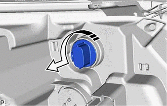
.png) |
Remove in this Direction |
(b) Remove the front turn signal light bulb from the front turn signal light socket.
2. REMOVE FRONT TURN SIGNAL LIGHT SOCKET (for Bulb Type Turn Signal Light)
3. REMOVE FRONT SIDE MARKER LIGHT BULB (for Bulb Type Turn Signal Light)
(a) Turn the front marker light socket plug with the front side marker light bulb as shown in the illustration to remove them as a unit.
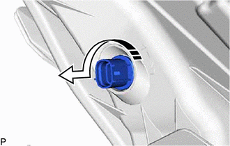
|
|
Remove in this Direction |
(b) Remove the front side marker light bulb from the front marker light socket plug.
4. REMOVE FRONT MARKER LIGHT SOCKET PLUG (for Bulb Type Turn Signal Light)
5. REMOVE HEADLIGHT BACK COVER (for LED Type Turn Signal Light)
(a) Turn the headlight back cover as shown in the illustration to remove it.
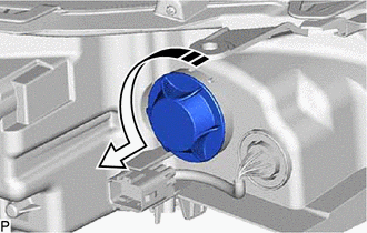
|
|
Remove in this Direction |
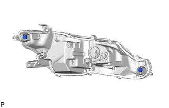
6. REMOVE HEADLIGHT COVER (for LED Type Turn Signal Light)
| (a) Remove the 2 headlight covers. |
|
READ NEXT:
 Inspection
INSPECTION PROCEDURE 1. INSPECT HEADLIGHT ASSEMBLY LH (for Bulb Type Turn Signal Light)
*a Component without harness connected
(Headlight Assembly LH) (a) Apply battery voltage
Adjustment
ADJUSTMENT CAUTION / NOTICE / HINT
HINT:
Use the same procedure for the RH side and LH side.
The following procedure is for the LH side.
PROCEDURE 1. PREPARE VEHICLE FOR HEADLIGHT A
Reassembly
REASSEMBLY CAUTION / NOTICE / HINT
HINT:
Use the same procedure for the RH side and LH side.
The following procedure is for the LH side.
PROCEDURE 1. INSTALL HEADLIGHT COVER (for LE
SEE MORE:
Dtc Check / Clear
DTC CHECK / CLEAR NOTICE: When the diagnosis system is changed from normal mode to check mode or vice versa, all DTCs and freeze frame data recorded in normal mode are cleared. Before changing modes, always check and make a note of DTCs and freeze frame data.
HINT:
DTCs which are stored in the
Inspection
INSPECTION PROCEDURE 1. INSPECT ENGINE OIL LEVEL SENSOR
(a) Measure the resistance according to the value(s) in the table below.
Standard Resistance:
Tester Connection Condition
Specified Condition
1 - Body ground ON
Below 1 Ω
OFF 10 kΩ
