Toyota Camry (XV70): Sliding Roof ECU Communication Stop (B1273)
DESCRIPTION
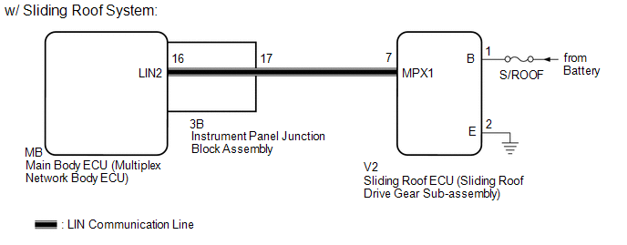
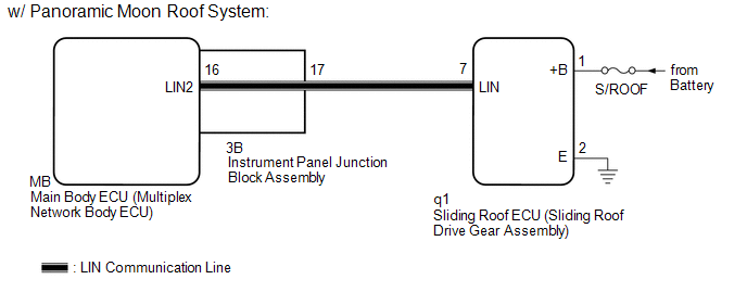
This DTC is stored when LIN communication between the sliding roof ECU (sliding roof drive gear sub-assembly)*1 or sliding roof ECU (sliding roof drive gear assembly)*2 and main body ECU (multiplex network body ECU) stops for 10 seconds or more.
|
DTC No. | Detection Item |
DTC Detection Condition | Trouble Area |
|---|---|---|---|
|
B1273 | Sliding Roof ECU Communication Stop |
No communication between sliding roof ECU (sliding roof drive gear sub-assembly)*1 or sliding roof ECU (sliding roof drive gear assembly)*2 and main body ECU (multiplex network body ECU) for 10 seconds or more. |
|
- *1: w/ Sliding Roof System
- *2: w/ Panoramic Moon Roof System
WIRING DIAGRAM
CAUTION / NOTICE / HINT
NOTICE:
- Inspect the fuses for circuits related to this system before performing the following procedure.
- Before replacing the main body ECU (multiplex network body ECU), refer to Registration.*1
Click here
.gif)
- When the sliding roof ECU (sliding roof drive gear sub-assembly) is replaced or removed and reinstalled, it is necessary to perform initialization.*2
Click here
- When the sliding roof ECU (sliding roof drive gear assembly) is replaced or removed and reinstalled, it is necessary to perform initialization.*3
Click here
- *1: w/ Smart Key System
- *2: w/ Sliding Roof System
- *3: w/ Panoramic Moon Roof System
PROCEDURE
|
1. | INSPECT INSTRUMENT PANEL JUNCTION BLOCK ASSEMBLY |
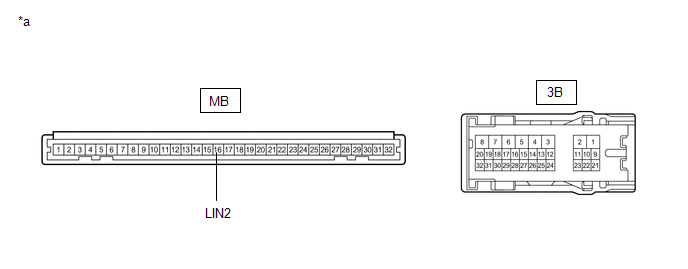
(a) Remove the instrument panel junction block assembly.
Click here
|
*a | Component without harness connected (Instrument Panel Junction Block Assembly) |
- | - |
(b) Remove the main body ECU (multiplex network body ECU) from the instrument panel junction block assembly.
(c) Measure the resistance according to the value(s) in the table below.
HINT:
This inspection is to check the LIN communication line in the instrument panel junction block assembly that connects the wire harness to the built-in main body ECU (multiplex network body ECU).
Standard Resistance:
|
Tester Connection | Condition |
Specified Condition |
|---|---|---|
|
3B-17 - MB-16 (LIN2) |
Always | Below 1 Ω |
|
Result | Proceed to |
|---|---|
|
OK (w/ Sliding Roof System) |
A |
| OK (w/ Panoramic Moon Roof System) |
B |
| NG |
C |
| B |
.gif) | GO TO STEP 6 |
| C |
| REPLACE INSTRUMENT PANEL JUNCTION BLOCK ASSEMBLY
|
|
.gif)
| 2. |
CHECK HARNESS AND CONNECTOR (INSTRUMENT PANEL JUNCTION BLOCK ASSEMBLY - SLIDING ROOF ECU (SLIDING ROOF DRIVE GEAR SUB-ASSEMBLY)) |
(a) Disconnect the V2 sliding roof ECU (sliding roof drive gear sub-assembly) connector.
(b) Measure the resistance according to the value(s) in the table below.
NOTICE:
Make sure that each ECU is in sleep mode before performing the inspection. To enter sleep mode, turn the ignition switch from ON to off and wait for 180 seconds or more without operating any switches.
Standard Resistance:
|
Tester Connection | Condition |
Specified Condition |
|---|---|---|
|
3B-17 - V2-7 (MPX1) | Ignition switch off |
Below 1 Ω |
|
V2-7 (MPX1) or 3B-17 - Body ground |
Ignition switch off | 10 kΩ or higher |
| NG | | REPAIR OR REPLACE HARNESS OR CONNECTOR |
|
| 3. |
CHECK HARNESS AND CONNECTOR (SLIDING ROOF ECU (SLIDING ROOF DRIVE GEAR SUB-ASSEMBLY) - BATTERY, BODY GROUND) |
(a) Measure the voltage according to the value(s) in the table below.
Standard Voltage:
|
Tester Connection | Condition |
Specified Condition |
|---|---|---|
|
V2-1 (B) - V2-2 (E) | Always |
11 to 14 V |
(b) Measure the resistance according to the value(s) in the table below.
Standard Resistance:
|
Tester Connection | Condition |
Specified Condition |
|---|---|---|
|
V2-2 (E) - Body ground |
Always | Below 1 Ω |
| NG | | REPAIR OR REPLACE HARNESS OR CONNECTOR |
|
| 4. |
REPLACE SLIDING ROOF ECU (SLIDING ROOF DRIVE GEAR SUB-ASSEMBLY) |
(a) Replace the sliding roof ECU (sliding roof drive gear sub-assembly).
Click here
|
| 5. |
CHECK FOR DTC |
(a) Clear the DTCs.
Body Electrical > Main Body > Clear DTCs(b) Recheck for DTCs.
Body Electrical > Main Body > Trouble CodesOK:
DTC B1273 is not output.
| OK | | END (SLIDING ROOF ECU (SLIDING ROOF DRIVE GEAR SUB-ASSEMBLY) WAS DEFECTIVE) |
| NG | | REPLACE MAIN BODY ECU (MULTIPLEX NETWORK BODY ECU)
|
| 6. |
CHECK HARNESS AND CONNECTOR (INSTRUMENT PANEL JUNCTION BLOCK ASSEMBLY - SLIDING ROOF ECU (SLIDING ROOF DRIVE GEAR ASSEMBLY)) |
(a) Disconnect the q1 sliding roof ECU (sliding roof drive gear assembly) connector.
(b) Measure the resistance according to the value(s) in the table below.
NOTICE:
Make sure that each ECU is in sleep mode before performing the inspection. To enter sleep mode, turn the ignition switch from ON to off and wait for 180 seconds or more without operating any switches.
Standard Resistance:
|
Tester Connection | Condition |
Specified Condition |
|---|---|---|
|
3B-17 - q1-7 (LIN) | Ignition switch off |
Below 1 Ω |
|
q1-7 (LIN) or 3B-17 - Body ground |
Ignition switch off | 10 kΩ or higher |
| NG | | REPAIR OR REPLACE HARNESS OR CONNECTOR |
|
| 7. |
CHECK HARNESS AND CONNECTOR (SLIDING ROOF ECU (SLIDING ROOF DRIVE GEAR ASSEMBLY) - BATTERY, BODY GROUND) |
(a) Measure the voltage according to the value(s) in the table below.
Standard Voltage:
|
Tester Connection | Condition |
Specified Condition |
|---|---|---|
|
q1-1 (+B) - q1-2 (E) |
Always | 11 to 14 V |
(b) Measure the resistance according to the value(s) in the table below.
Standard Resistance:
|
Tester Connection | Condition |
Specified Condition |
|---|---|---|
|
q1-2 (E) - Body ground |
Always | Below 1 Ω |
| NG | | REPAIR OR REPLACE HARNESS OR CONNECTOR |
|
| 8. |
REPLACE SLIDING ROOF ECU (SLIDING ROOF DRIVE GEAR ASSEMBLY) |
(a) Replace the sliding roof ECU (sliding roof drive gear assembly).
Click here
|
| 9. |
CHECK FOR DTC |
(a) Clear the DTCs.
Body Electrical > Main Body > Clear DTCs(b) Recheck for DTCs.
Body Electrical > Main Body > Trouble CodesOK:
DTC B1273 is not output.
| OK | | END (SLIDING ROOF ECU (SLIDING ROOF DRIVE GEAR ASSEMBLY) WAS DEFECTIVE) |
| NG | | REPLACE MAIN BODY ECU (MULTIPLEX NETWORK BODY ECU)
|
READ NEXT:
 Driver Side Door ECU Communication Stop (B2321)
DESCRIPTION This DTC is stored when LIN communication between the power window regulator motor assembly (for driver door) and main body ECU (multiplex network body ECU) stops for 10 seconds or more.
Front Passenger Side Door ECU Communication Stop (B2322)
DESCRIPTION This DTC is stored when LIN communication between the power window regulator motor assembly (for Front Passenger Door) and main body ECU (multiplex network body ECU) stops for 10 seconds o
Rear Door RH ECU Communication Stop (B2323)
DESCRIPTION This DTC is stored when LIN communication between the power window regulator motor assembly (for rear door RH) and main body ECU (multiplex network body ECU) stops for 10 seconds or more.
SEE MORE:
Tire Pressure Monitor ECU Communication Stop Mode
DESCRIPTION
Detection Item Symptom
Trouble Area Tire Pressure Monitor ECU Communication Stop Mode
Any of the following conditions are met:
Communication stop for "Tire Pressure" is indicated on the "Communication Bus Check" screen of the Techstream.
Click here
Customization
Customizable features
Your vehicle includes a variety of electronic features that can be
personalized to suit your preferences. The settings of these features
can be changed using the multi-information display, on the
audio system screen, or at your Toyota dealer.
Customizing vehicle features
