
Toyota Camry (XV70): Removal
REMOVAL
PROCEDURE
1. REMOVE WATER INLET WITH THERMOSTAT SUB-ASSEMBLY
Click here .gif)
2. REMOVE V-RIBBED BELT
Click here
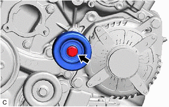
3. REMOVE NO. 2 IDLER PULLEY SUB-ASSEMBLY
| (a) Remove the bolt and No. 2 idler pulley sub-assembly. |
|
4. REMOVE WATER PUMP PULLEY
| (a) Using a screwdriver or equivalent with its tip wrapped in protective tape, hold the water pump pulley. |
|
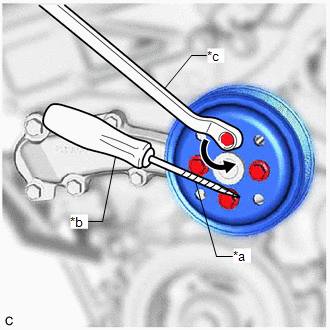
(b) Remove the 4 bolts and water pump pulley.
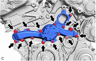
5. REMOVE ENGINE WATER PUMP ASSEMBLY
| (a) Remove the 15 bolts, engine water pump assembly and water pump gasket. |
|
READ NEXT:
 Installation
INSTALLATION PROCEDURE 1. INSTALL ENGINE WATER PUMP ASSEMBLY
(a) Install a new water pump gasket and the engine water pump assembly with the 15 bolts.
Torque: Bolt (A) : 43 N·m {438 kgf·c
SEE MORE:
How To Proceed With Troubleshooting
CAUTION / NOTICE / HINT
HINT:
Use the following procedure to troubleshoot the Entune system.
*: Use the Techstream.
PROCEDURE
1. VEHICLE BROUGHT TO WORKSHOP
NEXT
2.
CHECK THE CUSTOMER'S CONTRACT STATUS (a) Check if the satellite r
Installation
INSTALLATION PROCEDURE 1. INSTALL FLOW SHUTTING VALVE (NO. 1 WATER BY-PASS HOSE)
(a) Install the flow shutting valve (No. 1 water by-pass hose) with the bolt.
Torque: 19 N·m {194 kgf·cm, 14 ft·lbf} (b) Connect the flow shutting valve connector.
(c) Connect the flow shutting valve (No. 1 wa
© 2023-2026 Copyright www.tocamry.com
