Toyota Camry (XV70): Back-up Light Bulb
Components
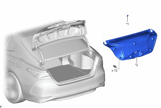
COMPONENTS
ILLUSTRATION
|
*1 | BACK-UP LIGHT BULB |
*2 | LUGGAGE COMPARTMENT DOOR COVER |
Removal
REMOVAL
CAUTION / NOTICE / HINT
HINT:
- Use the same procedure for the RH side and LH side.
- The following procedure is for the LH side.
PROCEDURE
1. REMOVE LUGGAGE COMPARTMENT DOOR COVER
Click here .gif)
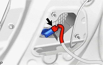
2. REMOVE BACK-UP LIGHT BULB
| (a) Disconnect the connector. |
|
(b) Turn the rear light socket plug with the back-up light bulb as shown in the illustration to remove them as a unit.
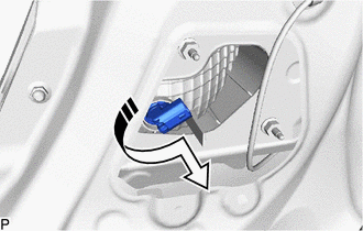
.png) |
Remove in this Direction |
(c) Remove the back-up light bulb from the rear light socket plug.
Installation
INSTALLATION
CAUTION / NOTICE / HINT
HINT:
- Use the same procedure for the RH side and LH side.
- The following procedure is for the LH side.
PROCEDURE
1. INSTALL BACK-UP LIGHT BULB
(a) Install the back-up light bulb to the rear light socket plug.
(b) Turn the rear light socket plug with the back-up light bulb as shown in the illustration to install them as a unit.
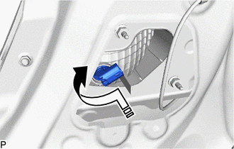
.png) |
Install in this Direction |
(c) Connect the connector.
2. INSTALL LUGGAGE COMPARTMENT DOOR COVER
Click here
.gif)
READ NEXT:
 Brake Fluid
ComponentsCOMPONENTS ILLUSTRATION
*1 BRAKE MASTER CYLINDER RESERVOIR FILLER CAP ASSEMBLY
- - ILLUSTRATION
*A except 2-Pot Caliper
*B for 2-Pot Caliper
Components
COMPONENTS ILLUSTRATION
*A for A25A-FKS
- -
*1 NO. 1 VACUUM HOSE CONNECTOR
*2 UNION TO CHECK VALVE HOSE
*3 VACUUM HOSE
*4 CLIP ILLUSTRATION
SEE MORE:
Removal
REMOVAL CAUTION / NOTICE / HINT
The necessary procedures (adjustment, calibration, initialization or registration) that must be performed after parts are removed and installed, or replaced during shift paddle switch (transmission shift switch assembly) removal/installation are shown below. Necessa
Components
COMPONENTS ILLUSTRATION
*1 FRONT CENTER UPPER SUSPENSION BRACE SUB-ASSEMBLY
- -
Tightening torque for "Major areas involving basic vehicle performance such as moving/turning/stopping" : N*m (kgf*cm, ft.*lbf)
N*m (kgf*cm, ft.*lbf): Specified torque
