
Toyota Camry (XV70): Brake Fluid
Components
COMPONENTS
ILLUSTRATION
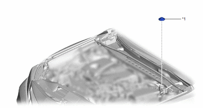
|
*1 | BRAKE MASTER CYLINDER RESERVOIR FILLER CAP ASSEMBLY |
- | - |
ILLUSTRATION
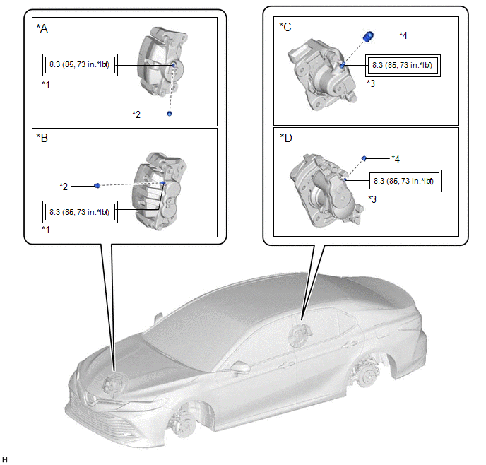
|
*A | except 2-Pot Caliper |
*B | for 2-Pot Caliper |
|
*C | w/o Electric Parking Brake System |
*D | w/ Electric Parking Brake System |
|
*1 | FRONT DISC BRAKE BLEEDER PLUG |
*2 | FRONT DISC BRAKE BLEEDER PLUG CAP |
|
*3 | REAR DISC BRAKE BLEEDER PLUG |
*4 | REAR DISC BRAKE BLEEDER PLUG CAP |
.png) |
Tightening torque for "Major areas involving basic vehicle performance such as moving/turning/stopping" : N*m (kgf*cm, ft.*lbf) |
- | - |
Replacement
REPLACEMENT
CAUTION / NOTICE / HINT
NOTICE:
- Move the shift lever to P and apply the parking brake before replacing the brake fluid.
- Add brake fluid to keep the level between the MIN and MAX lines of the reservoir while replacing the brake fluid.
- If brake fluid leaks onto any painted surface, immediately wash it off.
HINT:
If any work is performed on the brake system or if air in the brake lines is suspected, bleed the brake system.
PROCEDURE
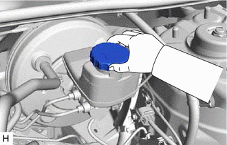
1. REMOVE BRAKE MASTER CYLINDER RESERVOIR FILLER CAP ASSEMBLY
| (a) Remove the brake master cylinder reservoir filler cap assembly. |
|
2. FILL RESERVOIR WITH BRAKE FLUID
(a) Fill the reservoir with brake fluid.
Brake Fluid:
SAE J1703 or FMVSS No. 116 DOT3
SAE J1704 or FMVSS No. 116 DOT4
NOTICE:
- Make sure that there is sufficient brake fluid in the reservoir.
- Do not remove the filter from the brake master cylinder reservoir and be sure to fill the brake master cylinder reservoir with new brake fluid to avoid any potential contamination of the brake system. Contamination, for example by dirt particles or mineral oil, could lead to functional brake problems.
3. REPLACE BRAKE FLUID
(a) Remove the bleeder plug cap.
(b) Connect a vinyl tube to the bleeder plug.
(c) Depress the brake pedal several times, and then loosen the bleeder plug with the pedal depressed.*1
(d) When fluid stops coming out, tighten the bleeder plug and release the brake pedal.*2
(e) Repeat steps *1 and *2 until new brake fluid comes out.
(f) Tighten the bleeder plug completely.
Torque:
8.3 N
READ NEXT:
 Components
COMPONENTS ILLUSTRATION
*A for A25A-FKS
- -
*1 NO. 1 VACUUM HOSE CONNECTOR
*2 UNION TO CHECK VALVE HOSE
*3 VACUUM HOSE
*4 CLIP ILLUSTRATION
Removal
REMOVAL PROCEDURE 1. REMOVE UNION TO CHECK VALVE HOSE (for A25A-FKS)
(a) Slide the clip and disconnect the union to check valve hose from the brake booster assembly.
(b)
SEE MORE:
Crankshaft Position - Camshaft Position Correlation Bank 1 Sensor B (P001700,P001900)
DESCRIPTION In the VVT (Variable Valve Timing) system, the appropriate exhaust valve open and close timing is controlled by the ECM. The ECM performs exhaust valve control by performing the following: 1) controlling the exhaust camshaft cam timing oil control solenoid assembly, camshaft timing gear
Sensor (Motor) Failure (B2341,B2344)
DESCRIPTION When the sliding roof ECU (sliding roof drive gear sub-assembly) detects a motor malfunction and the sliding roof operation is stopped, DTC B2341 is stored.
When the sliding roof ECU (sliding roof drive gear sub-assembly) detects a gear position malfunction and the sliding roof operat
