Toyota Camry (XV70): Components
Toyota Camry Repair Manual XV70 (2018-2024) / General / Maintenance / Brake Vacuum Hose / Components
COMPONENTS
ILLUSTRATION
|
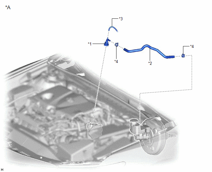
*A | for A25A-FKS |
- | - |
|
*1 | NO. 1 VACUUM HOSE CONNECTOR |
*2 | UNION TO CHECK VALVE HOSE |
|
*3 | VACUUM HOSE |
*4 | CLIP |
ILLUSTRATION
|
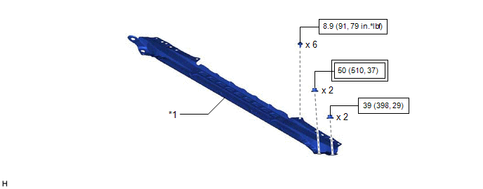
*A | for 2GR-FKS |
- | - |
|
*1 | FRONT CENTER UPPER SUSPENSION BRACE SUB-ASSEMBLY |
- | - |
.png) |
Tightening torque for "Major areas involving basic vehicle performance such as moving/turning/stopping" : N*m (kgf*cm, ft.*lbf) |
.png) |
N*m (kgf*cm, ft.*lbf): Specified torque |
ILLUSTRATION
|
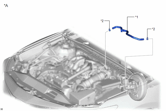
*A | for 2GR-FKS |
- | - |
|
*1 | UNION TO CHECK VALVE HOSE |
*2 | CLIP |
ILLUSTRATION
|
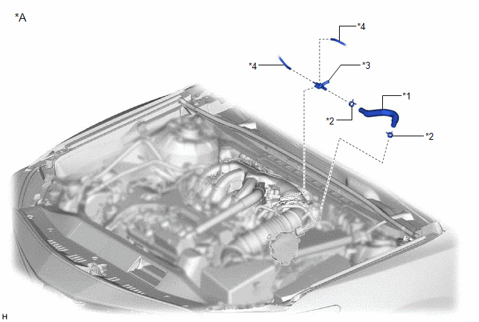
*A | for 2GR-FKS |
- | - |
|
*1 | AIR TUBE |
*2 | CLIP |
|
*3 | AIR DELIVERY WAY |
*4 | VACUUM TRANSMITTING HOSE ASSEMBLY |
READ NEXT:
 Removal
REMOVAL PROCEDURE 1. REMOVE UNION TO CHECK VALVE HOSE (for A25A-FKS)
(a) Slide the clip and disconnect the union to check valve hose from the brake booster assembly.
(b)
Installation
INSTALLATION PROCEDURE 1. INSTALL NO. 1 VACUUM HOSE CONNECTOR (for A25A-FKS)
(a) Align the No. 1 vacuum hose connector with the vacuum pump assembly, and push them together until the No. 1 vacuum ho
Differential Oil
ComponentsCOMPONENTS ILLUSTRATION
*1 REAR DIFFERENTIAL FILLER PLUG
*2 REAR DIFFERENTIAL DRAIN PLUG
*3 GASKET
- -
N*m (kgf*cm, ft.*lbf): Specified t
SEE MORE:
Removal
REMOVAL CAUTION / NOTICE / HINT
NOTICE: Make sure to hold the front wiper arm while lifting it as lifting the front wiper arm by the front wiper blade may damage or deform the front wiper blade. PROCEDURE
1. REMOVE FRONT WIPER ARM HEAD CAP
(a) Using a screwdriver, disengage the 3 claws
Inspection
INSPECTION PROCEDURE 1. INSPECT PARK/NEUTRAL POSITION SWITCH ASSEMBLY
NOTICE: Both the park/neutral position switch assembly and transmission control shaft lever are available in two different shapes due to design changes. As they are not compatible with each other, when replacing the park/neutral
© 2023-2026 Copyright www.tocamry.com
