Toyota Camry (XV70): Removal
REMOVAL
PROCEDURE
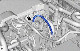
1. REMOVE UNION TO CHECK VALVE HOSE (for A25A-FKS)
| (a) Slide the clip and disconnect the union to check valve hose from the brake booster assembly. |
|
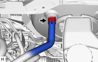
| (b) Slide the clip and disconnect the union to check valve hose from the No. 1 vacuum hose connector. |
|
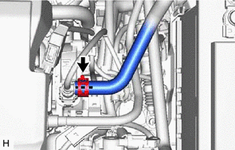
(c) Remove the 2 clips from the union to check valve hose.
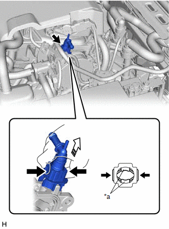
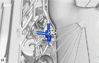
2. REMOVE NO. 1 VACUUM HOSE CONNECTOR (for A25A-FKS)
| (a) Disconnect the vacuum hose from the No. 1 vacuum hose connector. |
|
(b) Pinch the retainer of the No. 1 vacuum hose connector, and then pull the No. 1 vacuum hose connector off of the vacuum pump assembly.
NOTICE:
Be sure to remove the No. 1 vacuum hose connector by hand.
|
*a | Retainer |
.png) |
Pinch |
.png) |
Pull off |
3. REMOVE COWL TOP VENTILATOR LOUVER SUB-ASSEMBLY (for 2GR-FKS)
Click here .gif)
4. REMOVE FRONT CENTER UPPER SUSPENSION BRACE SUB-ASSEMBLY (for 2GR-FKS)
Click here
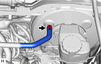
5. REMOVE UNION TO CHECK VALVE HOSE (for 2GR-FKS)
| (a) Disengage the clamp to separate the union to check valve hose from the air tube. |
|
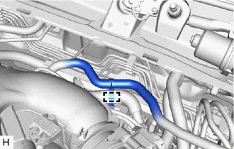
| (b) Slide the clip and disconnect the union to check valve hose from the brake booster assembly. |
|
| (c) Slide the clip and disconnect the union to check valve hose from the air delivery way. |
|

(d) Remove the 2 clips from the union to check valve hose.
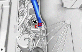
6. REMOVE AIR TUBE (for 2GR-FKS)
| (a) Disconnect the 2 vacuum transmitting hose assemblies from the air delivery way. |
|

| (b) Slide the clip and disconnect the air tube from the vacuum pump assembly. |
|
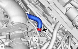
| (c) Slide the clip and disconnect the air tube from the air delivery way. |
|
(d) Remove the 2 clips from the air tube.
| (e) Disengage the clamp to remove the air delivery way from the intake air surge tank assembly. |
|
READ NEXT:
 Installation
INSTALLATION PROCEDURE 1. INSTALL NO. 1 VACUUM HOSE CONNECTOR (for A25A-FKS)
(a) Align the No. 1 vacuum hose connector with the vacuum pump assembly, and push them together until the No. 1 vacuum ho
Differential Oil
ComponentsCOMPONENTS ILLUSTRATION
*1 REAR DIFFERENTIAL FILLER PLUG
*2 REAR DIFFERENTIAL DRAIN PLUG
*3 GASKET
- -
N*m (kgf*cm, ft.*lbf): Specified t
SEE MORE:
Operation Check
OPERATION CHECK INPUT SIGNAL CHECK (a) Connect the Techstream to the DLC3.
(b) Check the cruise control main switch using the Data List function of the Techstream (cruise control main switch, -SET switch, +RES switch and CANCEL switch).
Click here INSPECT CRUISE CONTROL MAIN SWITCH
(a) Turn
Parts Location
PARTS LOCATION ILLUSTRATION
*1 ECM
*2 ENGINE ROOM RELAY BLOCK AND JUNCTION BLOCK ASSEMBLY
- ST RELAY - EFI-MAIN NO. 1 FUSE - J/B-B FUSE - ETCS FUSE ILLUSTRATION
*A w/ Shift Paddle Switch
- -
*1 SHIFT LOCK CONTROL UNIT ASSEMBLY
- TRANSMISSIO
