Toyota Camry (XV70): Telephone And Gps Antenna Cords (for Roof Side)
Components
COMPONENTS
ILLUSTRATION
|
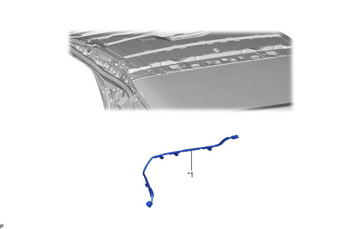
*1 | TELEPHONE AND GPS ANTENNA CORD |
- | - |
Removal
REMOVAL
CAUTION / NOTICE / HINT
The necessary procedures (adjustment, calibration, initialization, or registration) that must be performed after parts are removed and installed, or replaced during telephone and GPS antenna cord removal/installation are shown below.
Necessary Procedures After Parts Removed/Installed/Replaced|
Replaced Part or Performed Procedure |
Necessary Procedure | Effect/Inoperative Function when Necessary Procedure not Performed |
Link |
|---|---|---|---|
|
Disconnect cable from negative battery terminal |
Perform steering sensor zero point calibration. |
Lane Tracing Assist System |
|
|
Pre-collision System | |||
|
Memorize steering angle neutral point |
Parking Assist Monitor System |
| |
|
Panoramic View Monitor System |
|
CAUTION:
Some of these service operations affect the SRS airbag system. Read the precautionary notices concerning the SRS airbag system before servicing.
.png)
Click here
.gif)
PROCEDURE
1. REMOVE ROOF HEADLINING ASSEMBLY
Click here
2. REMOVE TELEPHONE AND GPS ANTENNA CORD
| (a) Disconnect the connector. |
|
.png)
(b) Disengage the 5 clamps to remove the telephone and GPS antenna cord.
Installation
INSTALLATION
PROCEDURE
1. INSTALL TELEPHONE AND GPS ANTENNA CORD
(a) Engage the 5 clamps.
(b) Connect the connector to install the telephone and GPS antenna cord.
2. INSTALL ROOF HEADLINING ASSEMBLY
Click here
.gif)
READ NEXT:
 Precaution
PRECAUTION PRECAUTION FOR DISCONNECTING CABLE FROM NEGATIVE BATTERY TERMINAL
NOTICE: When disconnecting the cable from the negative (-) battery terminal, initialize the following systems after the t
Parts Location
PARTS LOCATION ILLUSTRATION
*1 FRONT NO. 2 SPEAKER ASSEMBLY RH
*2 NAVIGATION ANTENNA ASSEMBLY
- Telephone Sub
*3 RADIO AND DISPLAY RECEIVER ASSEMBLY
*4 DCM (TE
SEE MORE:
ABS Solenoid Control Module Actuator Stuck On (C143A7E,C143A7F,C143D49,C14DA14)
DESCRIPTION The ABS solenoid relay is built into the skid control ECU in the brake actuator assembly. The ABS solenoid relay supplies power to each solenoid.
The skid control ECU (brake actuator assembly) detects an ABS solenoid relay malfunction by performing a self check and relay operation chec
Door Control Switch
ComponentsCOMPONENTS ILLUSTRATION
*1 DOOR CONTROL SWITCH ASSEMBLY
*2 POWER WINDOW REGULATOR SWITCH ASSEMBLY WITH FRONT DOOR UPPER ARMREST BASE PANEL RemovalREMOVAL PROCEDURE
1. REMOVE POWER WINDOW REGULATOR SWITCH ASSEMBLY WITH FRONT DOOR UPPER ARMREST BASE PANEL
Click here 2.
