Toyota Camry (XV70): Installation
INSTALLATION
PROCEDURE
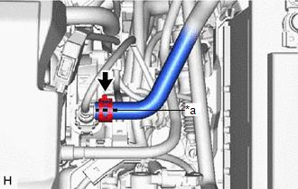
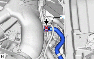
1. INSTALL NO. 1 VACUUM HOSE CONNECTOR (for A25A-FKS)
(a) Align the No. 1 vacuum hose connector with the vacuum pump assembly, and push them together until the No. 1 vacuum hose connector makes a "click" sound.
NOTICE:
- Check that there is no foreign matter on the connecting parts.
- After connecting the No. 1 vacuum hose connector, check that the vacuum pump assembly and No. 1 vacuum hose connector are securely connected by pulling on them.
(b) Connect the vacuum hose to the No. 1 vacuum hose connector.
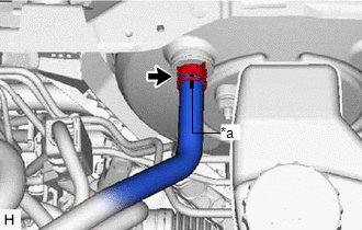
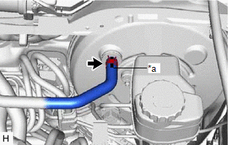
2. INSTALL UNION TO CHECK VALVE HOSE (for A25A-FKS)
(a) Install the 2 clips to the union to check valve hose.
| (b) Connect the union to check valve hose to the No. 1 vacuum hose connector, and slide the clip to secure it. NOTICE:
|
|
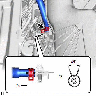
| (c) Connect the union to check valve hose to the brake booster assembly, and slide the clip to secure it. NOTICE:
|
|
3. INSTALL AIR TUBE (for 2GR-FKS)
| (a) Engage the clamp to install the air delivery way to the intake air surge tank assembly. |
|
.png)
(b) Install the 2 clips to the air tube.
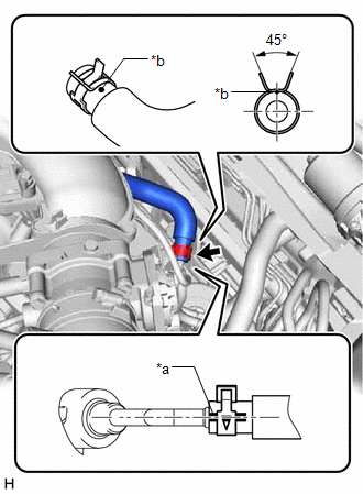
| (c) Connect the air tube to the air delivery way, and slide the clip to secure it. NOTICE:
|
|
| (d) Connect the air tube to the vacuum pump assembly, and slide the clip to secure it. NOTICE:
|
|
| (e) Connect the 2 vacuum transmitting hose assemblies to the air delivery way. |
|
.png)
4. INSTALL UNION TO CHECK VALVE HOSE (for 2GR-FKS)
(a) Install the 2 clips to the union to check valve hose.
| (b) Connect the union to check valve hose to the air delivery way, and slide the clip to secure it. NOTICE:
|
|
| (c) Connect the union to check valve hose to the brake booster assembly, and slide the clip to secure it. NOTICE:
|
|
| (d) Engage the clamp to install the union to check valve hose to the air tube. |
|
.png)
5. INSTALL FRONT CENTER UPPER SUSPENSION BRACE SUB-ASSEMBLY (for 2GR-FKS)
Click here .gif)
6. INSTALL COWL TOP VENTILATOR LOUVER SUB-ASSEMBLY (for 2GR-FKS)
Click here
READ NEXT:
 Differential Oil
ComponentsCOMPONENTS ILLUSTRATION
*1 REAR DIFFERENTIAL FILLER PLUG
*2 REAR DIFFERENTIAL DRAIN PLUG
*3 GASKET
- -
N*m (kgf*cm, ft.*lbf): Specified t
Components
COMPONENTS ILLUSTRATION
*1 FRONT FLEXIBLE HOSE
*2 GASKET
*3 BRAKE LINE
*4 FRONT SPEED SENSOR
*5 UNION BOLT
- -
Tightening torque
SEE MORE:
Intake Air Temperature Sensor 1 Bank 1 Circuit Short to Battery or Open (P011015)
DESCRIPTION Refer to DTC P011011. Click here
HINT: When DTC P011015 is stored, the ECM enters fail-safe mode. During fail-safe mode, the intake air temperature is estimated to be 20°C (68°F) by the ECM. Fail-safe mode continues until a pass condition is detected, and the engine switch is then
Glossary Of Sae And Toyota Terms
GLOSSARY OF SAE AND TOYOTA TERMS This glossary lists all SAE-J1930 terms and abbreviations used in this manual in compliance with SAE recommendations, as well as their TOYOTA equivalents.
SAE Abbreviation SAE Term
TOYOTA Term ( )-Abbreviation
A/C Air Conditioning
Air Con
