Toyota Camry owners & service manuals

Toyota Camry (XV70): System Diagram

SYSTEM DIAGRAM
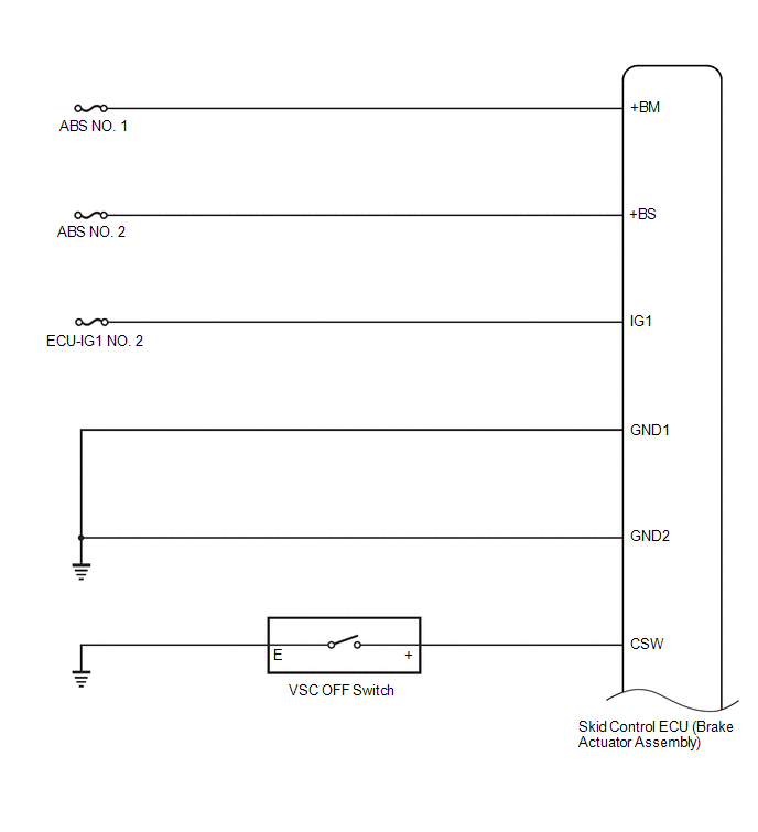
Transmitting ECU (Transmitter)

Receiving ECU

Signal

Communication Method

Skid control ECU (brake actuator assembly)

Steering angle sensor

Steering angle sensor request signal

CAN communication line

Steering angle sensor

Skid control ECU (brake actuator assembly)

Steering angle sensor signal

CAN communication line

Skid control ECU (brake actuator assembly)

Yaw rate and acceleration sensor (airbag sensor assembly)

Yaw rate and acceleration request signal

CAN communication line

Yaw rate and acceleration sensor (airbag sensor assembly)

Skid control ECU (brake actuator assembly)

Yaw rate and acceleration signal

CAN communication line

Skid control ECU (brake actuator assembly)

ECM

  • Wheel speed signal
  • VSC data signal

CAN communication line

ECM

Skid control ECU (brake actuator assembly)

  • Shift position signal
  • Throttle position signal
  • Engine speed signal

CAN communication line

Skid control ECU (brake actuator assembly)

Power steering ECU (rack and pinion power steering gear assembly)

  • Wheel speed signal
  • VSC data signal

CAN communication line

Main body ECU (multiplex network body ECU)

Skid control ECU (brake actuator assembly)

Parking brake switch assembly signal

CAN communication line

Skid control ECU (brake actuator assembly)

Combination meter assembly

  • ABS warning light signal
  • Brake system warning light (red indicator) signal
  • VSC OFF indicator light signal
  • Multi-information display (Traction Control Turned Off) signal
  • Multi-information display (Secondary Collision Brake System Malfunction) signal
  • Slip indicator light signal
  • Vehicle speed signal

CAN communication line

Airbag sensor assembly

Skid control ECU (brake actuator assembly)

Secondary collision brake request signal

CAN communication line

    READ NEXT:

     How To Proceed With Troubleshooting

    CAUTION / NOTICE / HINT HINT: *: Use the Techstream. PROCEDURE 1. VEHICLE BROUGHT TO WORKSHOP NEXT 2. CUSTOMER PROBLEM ANALYSIS (a) Interview

     Check For Intermittent Problems

    CHECK FOR INTERMITTENT PROBLEMS CHECK FOR INTERMITTENT PROBLEMS HINT: A momentary interruption (open circuit) in the connectors and/or wire harness between the sensors and ECUs can be detected using

     Calibration

    CALIBRATION DESCRIPTION (a) Refer to the table below and then perform the necessary operation according to the part to be replaced in order to perform calibration. Parts to be Replaced / Operati

    SEE MORE:

     Problem Symptoms Table

    PROBLEM SYMPTOMS TABLE NOTICE: Depending on the parts that are replaced during vehicle inspection or maintenance, performing initialization, registration or calibration may be needed. Refer to Precaution for Audio and Visual System. Click here When replacing the radio and display receive

     Adjusting the set speed - Dynamic radar cruise control with full-speed range

    Adjusting the set speed by the switch To change the set speed, press the "+ RES" or "- SET" switch until the desired set speed is displayed. Increases the speed (Except when the vehicle has been stopped by system control in vehicle- to-vehicle distance control mode) Decreases th

    © 2023-2025 Copyright www.tocamry.com