Toyota Camry (XV70): Installation
INSTALLATION
PROCEDURE
1. INSTALL STUD BOLT
HINT:
If a stud bolt is deformed or its threads are damaged, replace it.
| (a) Using an E8 "TORX" socket wrench, install the 2 stud bolts to the exhaust manifold assembly LH (TWC: Front Catalyst). Torque: 19.5 N·m {199 kgf·cm, 14 ft·lbf} |
|
.png)
2. INSTALL EXHAUST MANIFOLD TO HEAD GASKET (for Bank 2)
(a) Install a new exhaust manifold to head gasket (for Bank 2) to the cylinder head sub-assembly.
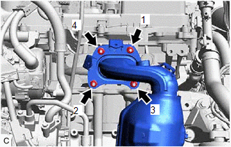
3. INSTALL EXHAUST MANIFOLD ASSEMBLY LH (TWC: Front Catalyst)
(a) Temporarily install the exhaust manifold assembly LH (TWC: Front Catalyst) with the 4 nuts.
(b) Temporarily install the No. 2 manifold stay to the exhaust manifold assembly LH (TWC: Front Catalyst) and cylinder block sub-assembly with the bolt and nut.
| (c) Using a 12 mm deep socket wrench, tighten the 4 nuts in the order shown in the illustration. Torque: 21 N·m {214 kgf·cm, 15 ft·lbf} |
|
(d) Tighten the bolt and nut in the order shown in the illustration.
.png) |
Bolt |
.png) |
Nut |
Torque:
Nut :
35 N·m {357 kgf·cm, 26 ft·lbf}
Bolt :
34 N·m {347 kgf·cm, 25 ft·lbf}
4. CONNECT NO. 5 WATER BY-PASS HOSE
(a) Engage the 2 clamps to connect the No. 5 water by-pass hose and No. 6 water by-pass hose to the hose clamp.
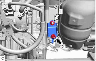
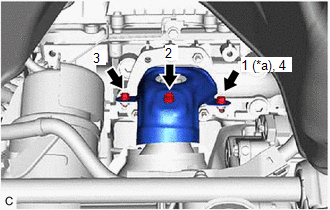
5. INSTALL NO. 2 EXHAUST MANIFOLD HEAT INSULATOR
| (a) Install the No. 2 exhaust manifold heat insulator to the exhaust manifold assembly LH (TWC: Front Catalyst) with the 3 bolts in the order shown in the illustration. Torque: 8.5 N·m {87 kgf·cm, 75 in·lbf} |
|
6. INSTALL ENGINE OIL LEVEL DIPSTICK GUIDE
Click here
.gif)
7. INSTALL AIR FUEL RATIO SENSOR (for Bank 2)
Click here
8. INSTALL COOL AIR INTAKE DUCT SEAL
Click here
9. INSTALL V-BANK COVER SUB-ASSEMBLY
Click here
10. INSTALL EXHAUST MANIFOLD TO HEAD GASKET (for Bank 1)
(a) Install a new exhaust manifold to head gasket (for Bank 1) to the cylinder head sub-assembly RH.
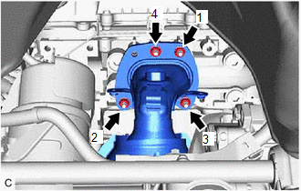
11. INSTALL EXHAUST MANIFOLD ASSEMBLY RH (TWC: Front Catalyst)
(a) Temporarily install the exhaust manifold assembly RH (TWC: Front Catalyst) with the 4 nuts.
| (b) Using a 12 mm deep socket wrench, tighten the 4 nuts in the order shown in the illustration. Torque: 21 N·m {214 kgf·cm, 15 ft·lbf} |
|
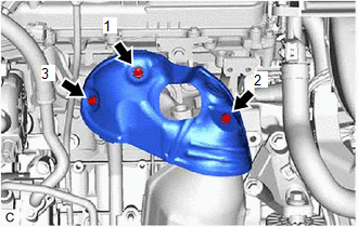
12. INSTALL NO. 1 EXHAUST MANIFOLD HEAT INSULATOR
| (a) Install the No. 1 exhaust manifold heat insulator to the exhaust manifold assembly (TWC: Front Catalyst) with the 3 bolts in the order shown in the illustration. Torque: 8.5 N·m {87 kgf·cm, 75 in·lbf} |
|
13. INSTALL AIR FUEL RATIO SENSOR (for Bank 1)
Click here
14. INSTALL FRONT EXHAUST PIPE ASSEMBLY
(a) Install 3 new gaskets to the front exhaust pipe assembly (TWC: Rear Catalyst).
(b) Connect the front exhaust pipe assembly (TWC: Rear Catalyst) to the exhaust pipe support.
(c) Install the front exhaust pipe assembly (TWC: Rear Catalyst) with 4 new bolts and 4 new nuts.
(d) Engage the 2 wire harness clamps.
(e) Connect the 2 heated oxygen sensor connectors.
15. INSTALL NO. 1 EXHAUST PIPE SUPPORT BRACKET (for Lower Side)
Click here
16. INSTALL BODY MOUNTING PLATE
Click here
17. INSTALL FRONT FLOOR COVER LH
Click here
18. INSTALL FRONT FLOOR COVER RH
Click here
19. INSPECT FOR EXHAUST GAS LEAK
Click here
20. INSTALL REAR ENGINE UNDER COVER RH
Click here
21. INSTALL NO. 1 ENGINE UNDER COVER
Click here
22. INSTALL FRONT WHEEL OPENING EXTENSION PAD LH
Click here
23. INSTALL FRONT WHEEL OPENING EXTENSION PAD RH
Click here
READ NEXT:
 Components
COMPONENTS ILLUSTRATION
*1 FRONT FLOOR COVER LH
*2 FRONT FLOOR COVER RH
N*m (kgf*cm, ft.*lbf): Specified torque
- - ILLUSTRATION
*1 NO. 1 ENG
Removal
REMOVAL CAUTION / NOTICE / HINT
The necessary procedures (adjustment, calibration, initialization or registration) that must be performed after parts are removed and installed, or replaced during ex
Installation
INSTALLATION PROCEDURE 1. INSTALL STUD BOLT
HINT: If a stud bolt is deformed or its threads are damaged, replace it.
(a) Using an E8 "TORX" socket wrench, install the 2 stud bolts to the exhau
SEE MORE:
Calibration
CALIBRATION DESCRIPTION (a) Refer to the table below and then perform the necessary operation according to the part to be replaced in order to perform calibration.
Parts to be Replaced / Operation
Necessary Operation
Skid control ECU (brake actuator assembly)
Perform acceler
Components
COMPONENTS ILLUSTRATION
*1 LUGGAGE COMPARTMENT DOOR EMBLEM
*2 NO. 2 LUGGAGE COMPARTMENT DOOR NAME PLATE
● Non-reusable part
- - ILLUSTRATION
*1 NO. 3 LUGGAGE COMPARTMENT DOOR PLATE
- -
● Non-reusable part
