Toyota Camry (XV70): Components
COMPONENTS
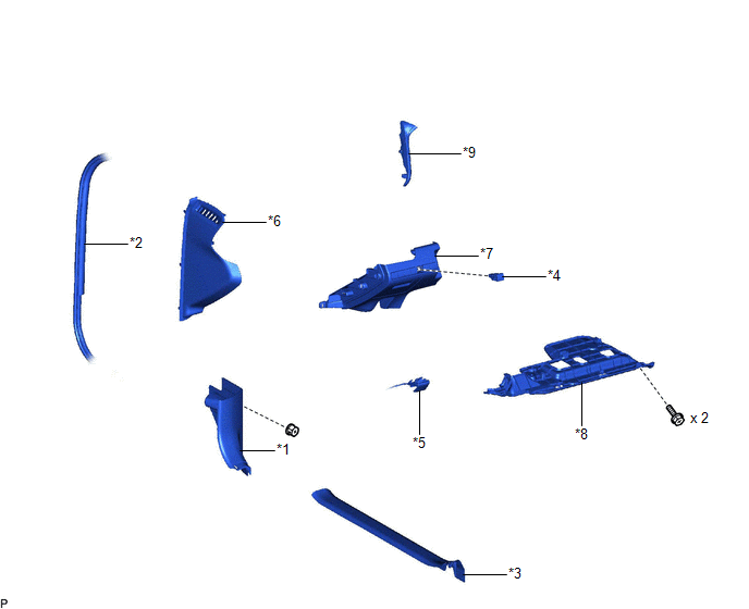
ILLUSTRATION
|
*1 | COWL SIDE TRIM SUB-ASSEMBLY LH |
*2 | FRONT DOOR OPENING TRIM WEATHERSTRIP LH |
|
*3 | FRONT DOOR SCUFF PLATE LH |
*4 | FUEL LID OPENER SWITCH |
|
*5 | HOOD LOCK CONTROL LEVER SUB-ASSEMBLY |
*6 | INSTRUMENT SIDE PANEL LH |
|
*7 | NO. 1 INSTRUMENT PANEL SUB-ASSEMBLY |
*8 | NO. 1 INSTRUMENT PANEL UNDER COVER SUB-ASSEMBLY |
|
*9 | NO. 2 METER HOOD CLUSTER |
- | - |
READ NEXT:
 Removal
REMOVAL PROCEDURE 1. REMOVE FRONT DOOR SCUFF PLATE LH
Click here
2. REMOVE COWL SIDE TRIM SUB-ASSEMBLY LH Click here
3. DISCONNECT FRONT DOOR OPENING TRIM WE
Inspection
INSPECTION PROCEDURE 1. INSPECT FUEL LID OPENER SWITCH
(a) Check the switch. (1) Measure the resistance according to the value(s) in the table below.
Standard Resistance:
Tester Co
Installation
INSTALLATION PROCEDURE 1. INSTALL FUEL LID OPENER SWITCH
(a) Engage the 2 claws to install the fuel lid opener switch as shown in the illustration.
Install in this Direction
SEE MORE:
Low Pressure Fuel System Pressure - Too High (P008B00)
DESCRIPTION Refer to DTC P008A00. Click here
DTC No. Detection Item
DTC Detection Condition Trouble Area
MIL Memory
Note P008B00
Low Pressure Fuel System Pressure - Too High
Actual fuel pressure (for low pressure side) value higher than target fuel pres
Installation
INSTALLATION CAUTION / NOTICE / HINT
HINT: Use the same procedure for the No. 2 parking brake cable assembly and No. 3 parking brake cable assembly. PROCEDURE
1. INSTALL NO. 1 PARKING BRAKE CABLE CLAMP
(a) Install a new No. 1 parking brake cable clamp to the No. 3 parking brake cable assembly
© 2023-2026 Copyright www.tocamry.com
