Toyota Camry (XV70): Installation
INSTALLATION
PROCEDURE
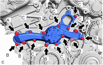
1. INSTALL ENGINE WATER PUMP ASSEMBLY
| (a) Install a new water pump gasket and the engine water pump assembly with the 15 bolts. Torque: Bolt (A) : 43 N·m {438 kgf·cm, 32 ft·lbf} Bolt (B) : 21 N·m {214 kgf·cm, 15 ft·lbf} Bolt (C) : 11 N·m {112 kgf·cm, 8 ft·lbf} Standard Length:
NOTICE:
|
|
2. INSTALL WATER PUMP PULLEY
(a) Temporarily install the water pump pulley with the 4 bolts.
| (b) Using a screwdriver or equivalent with its tip wrapped in protective tape, hold the water pump pulley. |
|
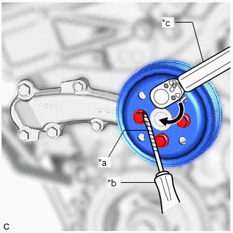
(c) Fully tighten the 4 bolts.
Torque:
21 N·m {214 kgf·cm, 15 ft·lbf}
3. INSTALL NO. 2 IDLER PULLEY SUB-ASSEMBLY
(a) Install the No. 2 idler pulley sub-assembly with the bolt.
Torque:
54 N·m {551 kgf·cm, 40 ft·lbf}
4. INSTALL V-RIBBED BELT
Click here .gif)
5. INSTALL WATER INLET WITH THERMOSTAT SUB-ASSEMBLY
Click here
READ NEXT:
 Components
COMPONENTS ILLUSTRATION
*1 FRONT FLOOR COVER LH
*2 FRONT FLOOR COVER RH
N*m (kgf*cm, ft.*lbf): Specified torque
- - ILLUSTRATION
*1 CENTER FL
SEE MORE:
Precaution
PRECAUTION PRECAUTION FOR DISCONNECTING CABLE FROM NEGATIVE BATTERY TERMINAL
NOTICE: When disconnecting the cable from the negative (-) battery terminal, initialize the following systems after the cable is reconnected.
System Name See Procedure
Lane Tracing Assist System
Manual air conditioning
system
Air conditioning controls
■ Adjusting the temperature setting
To adjust the temperature setting, turn
clockwise to
increase the temperature and counterclockwise to decrease the
temperature.
If is not pressed, the system
will blow ambient temperature air or
heated air.
■ Fan
