Toyota Camry (XV70): Components
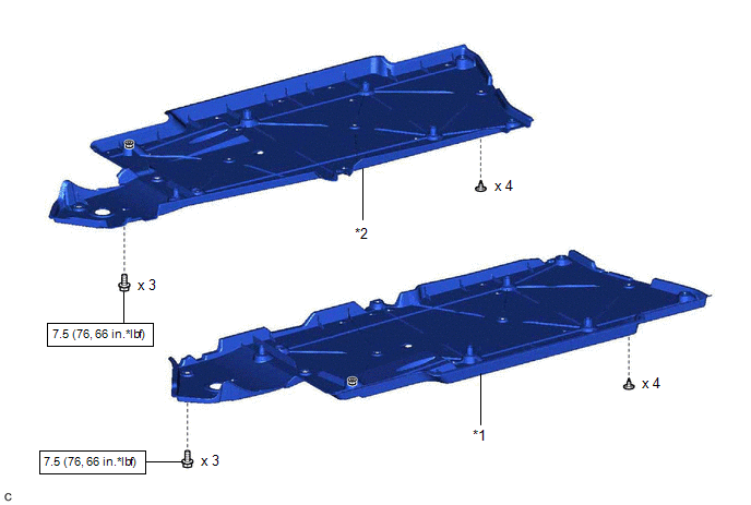
COMPONENTS
ILLUSTRATION
|
*1 | FRONT FLOOR COVER LH |
*2 | FRONT FLOOR COVER RH |
.png) |
N*m (kgf*cm, ft.*lbf): Specified torque |
- | - |
ILLUSTRATION
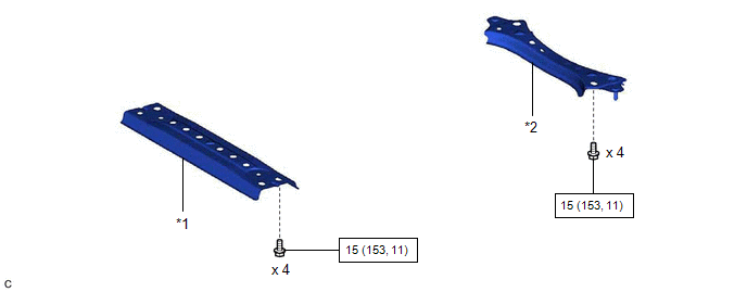
|
*1 | CENTER FLOOR CROSSMEMBER BRACE |
*2 | FRONT CENTER FLOOR BRACE |
|
|
N*m (kgf*cm, ft.*lbf): Specified torque |
- | - |
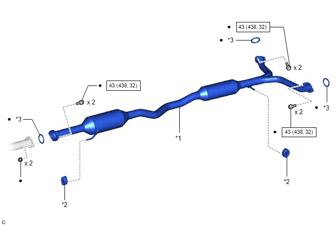
ILLUSTRATION
|
*1 | CENTER EXHAUST PIPE ASSEMBLY |
*2 | EXHAUST PIPE SUPPORT |
|
*3 | GASKET |
- | - |
|
|
N*m (kgf*cm, ft.*lbf): Specified torque |
● | Non-reusable part |
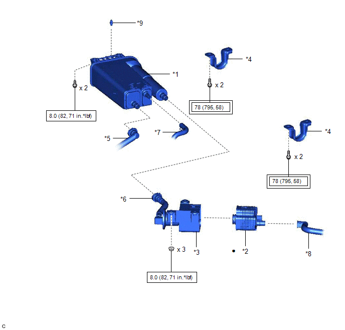
ILLUSTRATION
|
*1 | CANISTER (CHARCOAL CANISTER ASSEMBLY) |
*2 | LEAK DETECTION PUMP SUB-ASSEMBLY |
|
*3 | NO. 2 CHARCOAL CANISTER SUB-ASSEMBLY |
*4 | REAR NO. 1 STABILIZER BAR BRACKET |
|
*5 | FUEL TANK VENT HOSE |
*6 | VENT LINE HOSE |
|
*7 | PURGE LINE HOSE |
*8 | AIR LINE TUBE |
|
*9 | CLIP |
- | - |
.png) |
Tightening torque for "Major areas involving basic vehicle performance such as moving/turning/stopping": N*m (kgf*cm, ft.*lbf) |
|
N*m (kgf*cm, ft.*lbf): Specified torque |
|
● | Non-reusable part |
- | - |
READ NEXT:
 Removal
REMOVAL CAUTION / NOTICE / HINT
The necessary procedures (adjustment, calibration, initialization or registration) that must be performed after parts are removed and installed, or replaced during ca
Inspection
INSPECTION PROCEDURE 1. INSPECT CANISTER (CHARCOAL CANISTER ASSEMBLY)
(a) Visually check the canister (charcoal canister assembly).
(1) Visually check the canister (charcoal canister assembly
Installation
INSTALLATION PROCEDURE 1. INSTALL LEAK DETECTION PUMP SUB-ASSEMBLY
HINT: Only perform this procedure when replacement of the leak detection pump sub-assembly is necessary.
(a) Engage the 2 cla
SEE MORE:
Panel Switches do not Function
CAUTION / NOTICE / HINT
NOTICE:
Depending on the parts that are replaced during vehicle inspection or maintenance, performing initialization, registration or calibration may be needed. Refer to Precaution for Audio and Visual System.
Click here
When replacing the radio and display rec
Removal
REMOVAL PROCEDURE 1. REMOVE NO. 1 INSTRUMENT PANEL UNDER COVER SUB-ASSEMBLY
Click here
2. REMOVE STOP LIGHT SWITCH ASSEMBLY
(a) Disconnect the connector.
(b) Turn the stop light switch assembly counterclockwise and remove it.
Remove in thi
